135
Operating Procedure Section 4-2
The following table shows the addresses used for analog output.
Note 1. The addresses are set according to the unit number of the Special I/O Unit.
Refer to 4-3-2 Unit Number Switch for further details.
2. Set as required.
Output number Output signal
range
Output setting
address
(n = CIO 2010)
See note 1.
Original
conversion
address
1 1 to 5 V (n+1) = CIO 2011 D00200
2 0 to 10 V (n+2) = CIO 2012 D00201
3 –10 to 10 V (n+3) = CIO 2013 D00202
4 Not used. --- ---
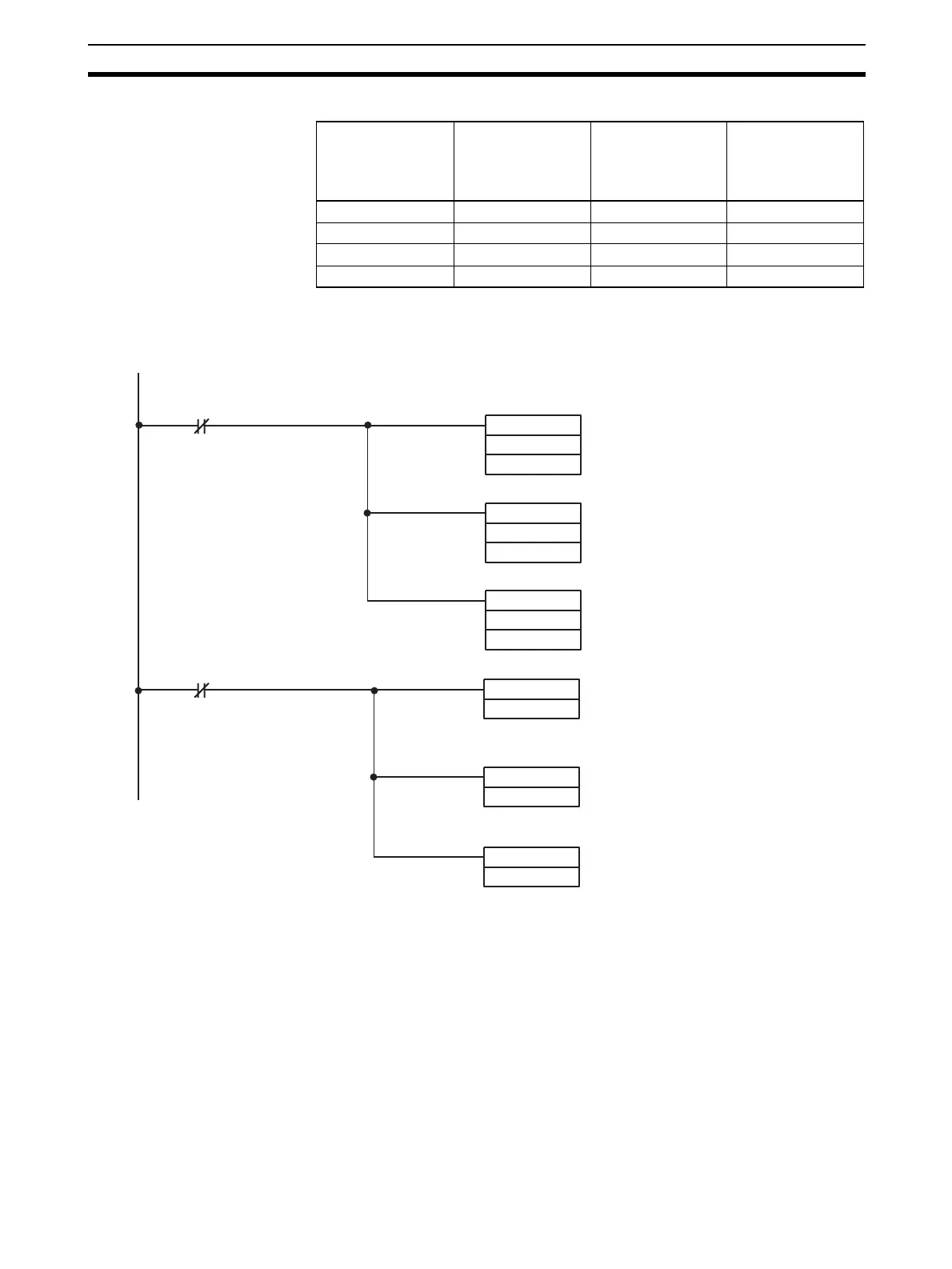
D00200 is set in word CIO 2011.
D00201 is set in word CIO 2012.
D00202 is set in word CIO 2013.
To start analog output, turn ON the
Conversion Enable Bits 201000 to
201002 (bits 00 to 03 of word
CIO 2010).
The data in words CIO 2011 and
2012 will be output as 1 to 5 V, and
CIO the data in CIO 2013 will be
output as –10 to 10 V.
MOV (021)
D00200
2011
MOV (021)
D00201
2012
Execution condition
MOV (021)
D00202
2013
SET
201000
SET
201002
SET
201001
Execution condition
See 4-6-2 Starting and Stopping
Conversion
for details.
 Loading...


