247
Exchanging Data with the CPU Unit Section 6-5
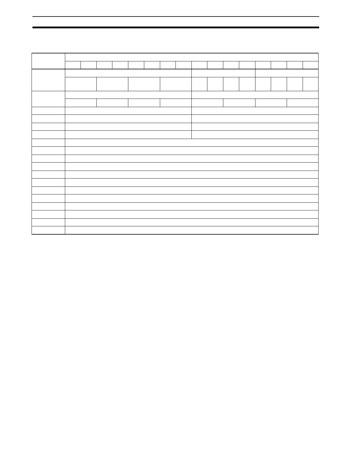
DM Allocation Contents The following table shows the allocation of DM words and bits for both normal
and adjustment mode.
Note For the DM word addresses, m = D20000 + (unit number x 100).
DM word Bits
1514131211109876543210
D(m) Ratio conversion use setting Input use setting Output use setting
Loop 4 Loop 3 Loop 2 Loop 1 Input
4
Input
3
Input
2
Input
1
Out-
put 4
Out-
put 3
Out-
put 2
Out-
put 1
D(m+1) Input signal range setting Output signal range setting
Input 4 Input 3 Input 2 Input 1 Output 4 Output 3 Output 2 Output 1
D(m+2) Not used. Output 1: Output status when conversion stopped
D(m+3) Not used. Output 2: Output status when conversion stopped
D(m+4) Not used. Output 3: Output status when conversion stopped
D(m+5) Not used. Output 4: Output status when conversion stopped
D(m+6) Input 1: Mean value processing setting
D(m+7) Input 2: Mean value processing setting
D(m+8) Input 3: Mean value processing setting
D(m+9) Input 4: Mean value processing setting
D(m+10) Loop 1 (input 1 to output 1), A constant
D(m+11) Loop 1 (input 1 to output 1), B constant
D(m+12) Loop 2 (input 2 to output 2), A constant
D(m+13) Loop 2 (input 2 to output 2), B constant
D(m+14) Loop 3 (input 3 to output 3), A constant
D(m+15) Loop 3 (input 3 to output 3), B constant
D(m+16) Loop 4 (input 4 to output 4), A constant
D(m+17) Loop 4 (input 4 to output 4), B constant
 Loading...


