248
Exchanging Data with the CPU Unit Section 6-5
Set Values and Stored Values
Note 1. The input signal range of “1 to 5 V” and “4 to 20 mA” is switched using the
pins of the voltage/current switch. Refer to 6-3-4 Voltage/Current Switch for
details.
2. For the range of
±10 V, the output is 0 V. For other output signal ranges,
the minimum value of each signal range is output. Refer to 6-7-2 Output
Hold Function for details.
3. The default of mean value processing setting is set to “Mean value pro-
cessing for 2 buffers.” Refer to 6-6-2 Mean Value Processing.
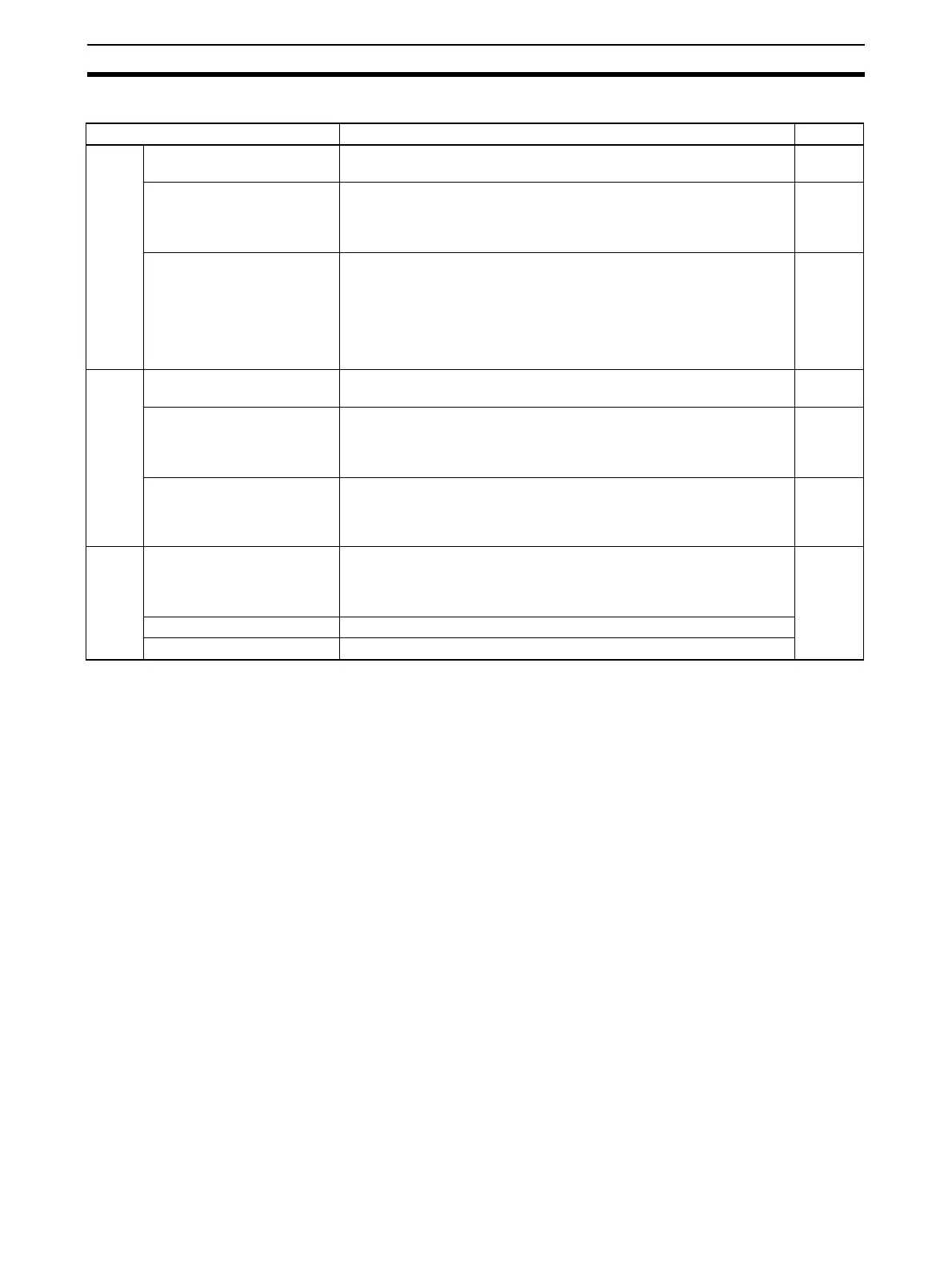
Item Contents Page
Input Use setting 0: Not used.
1: Used.
252
Input signal range 00: –10 to 10 V
01: 0 to 10 V
10: 1 to 5 V/4 to 20 mA (See note 1.)
11: 0 to 5 V
253
Mean value processing set-
ting
0000: Mean value processing for 2 buffers (See note 3.)
0001: No mean value processing
0002: Mean value processing for 4 buffers
0003: Mean value processing for 8 buffers
0004: Mean value processing for 16 buffers
0005: Mean value processing for 32 buffers
0006: Mean value processing for 64 buffers
254
Output Use setting 0: Not used.
1: Used.
259
Output signal range 00: –10 to 10 V
01: 0 to 10 V
10: 1 to 5 V
11: 0 to 5 V
259
Output status when stopped 00: CLR Outputs 0 or minimum value of each range.
(See note 2.)
01: HOLD Holds output just before stopping.
02: MAX Outputs maximum value of range.
261
Loop Ratio conversion use setting 00: Not used.
01: Uses positive gradient conversion.
10: Uses negative gradient conversion.
11: Same as for setting “00” above.
262
A constant 4 digits BCD (0 to 9999)
B constant 16-bit binary data
 Loading...


