24
Operating Procedure Section 2-2
Initial Data Settings
1,2,3... 1. Specify the Special I/O Unit DM Area settings. Refer to 2-5-4 Fixed Data
Allocations for further details.
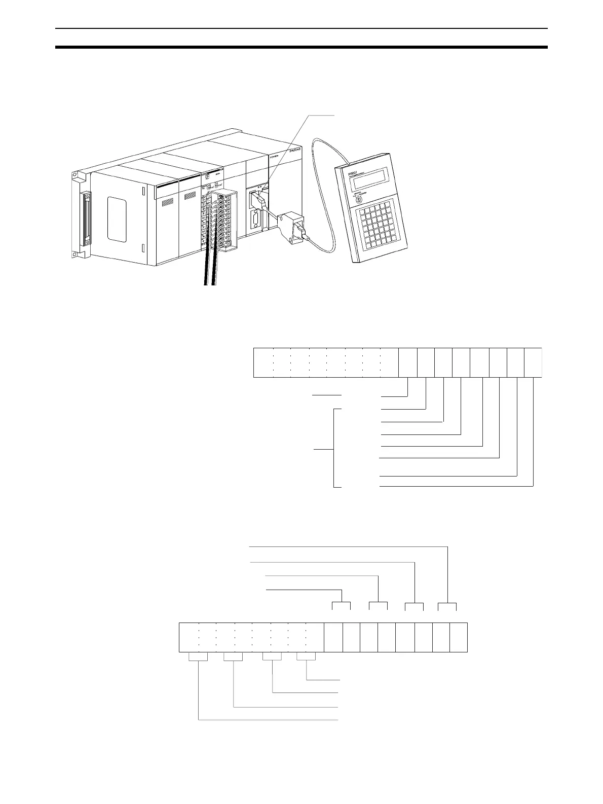
• The following diagram shows the input settings used. Refer to DM Al-
location Contents on page 41 and 2-6-1 Input Settings and Conversion
Values for more details.
• The following diagram shows the input range settings. Refer to DM Al-
location Contents on page 41 and 2-6-1 Input Settings and Conversion
Values for more details.
Also set DM word m+52 when using current input with the CS1W-AD161.
Peripheral port
Setting conditions
Unit No. 1
Analog input 1: 1 to 5 V
Analog input 2: 1 to 5 V
Analog input 3: 4 to 20 mA
Analog input 4: 4 to 20 mA
Analog input 5: 0 to 10 V
Analog input 6: 0 to 10 V
Analog input 7: –10 to 10 V
Analog input 8: Not used.
15 14 13 12 11 10 09 08 07 06 05 01 0004 03 02
0 0 0 0 0 0 0 0 0 1 1 1 1 1 1 1
Bit
Input 4
Input 3
Input 2
Input 1
Used
m: D20100
(007F Hex)
Not used
Input 8
Input 7
Input 6
Input 5
15 14 13 12 11 10 09 08 07 06 05 01 0004 03 02
0 0 0 0 0 1 0 1 1 0 1 0 1 0 1 0
Bit
m+1: D20101
(05AA Hex)
Input 1: 1 to 5 V. Set to 10.
Input 2: 1 to 5 V. Set to 10.
Input 3: 4 to 20 mA. Set to 10.
Input 4: 4 to 20 mA. Set to 10.
Input 5: 0 to 10 V. Set to 01.
Input 6: 0 to 10 V. Set to 01.
Input 7: −10 to 10 V. Set to 00.
Input 8: Not used. Set to 00 (disabled)
 Loading...


