98
Power Supply Wiring Section 4-4
Allowable Currents for
Cables
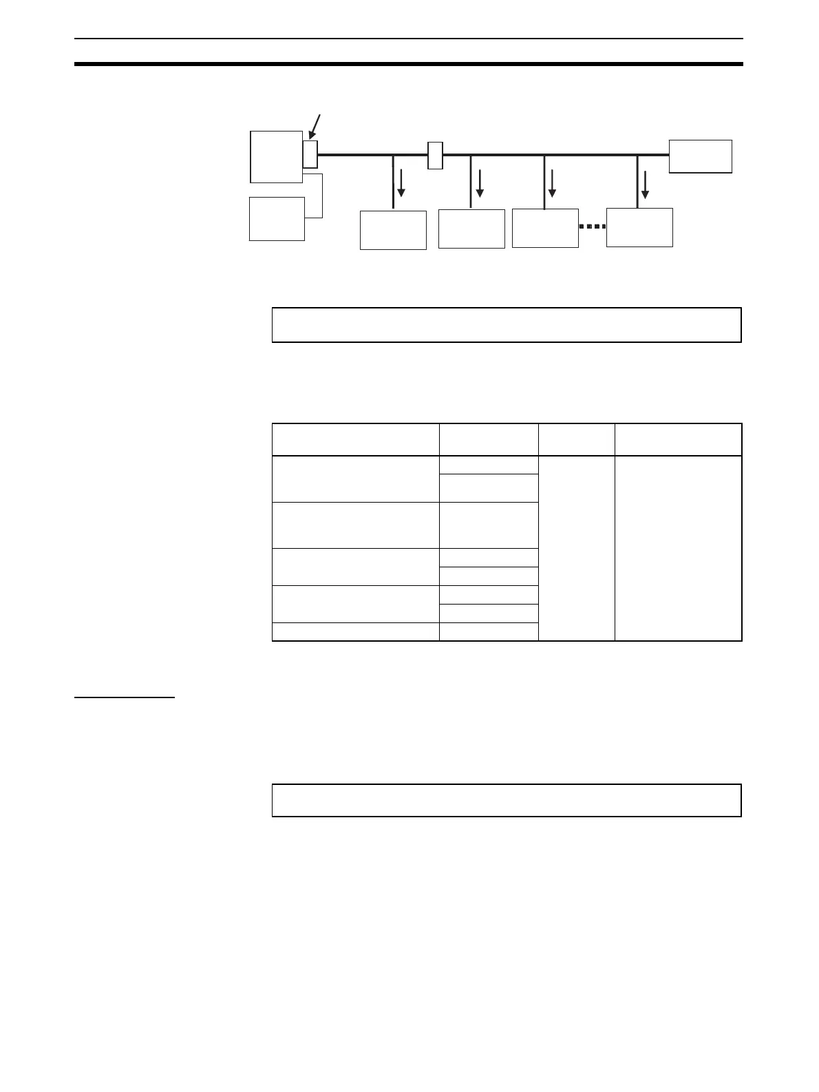
Select the communications cable so that the total current consumption of all
Slave Units does not exceed the allowable current of the cable.
Allowable Currents for
Connectors
There are limits to the allowable current for the communications power supply
connectors on the Master Unit and Repeater Units, Flat Connector Sockets,
and Flat Connector Plugs. Do not allow the current flow where these connec-
tors are used to exceed the allowable current.
Note If the allowable current is exceeded, heating and burning may result.
Voltage Drop
Cable Voltage Drop The voltage drop must be considered so that the power supply voltage at the
Slave Unit that is the farthest from the power supply will still be within the
allowable power supply range.
The voltage drop is expressed by the following formula.
If the voltage drop is too large and power cannot be supplied to the farthest
Slave Unit within the allowable range, add a Repeater Unit and supply power
from the Repeater Unit.
Master
Unit
Power
supply,
24 VDC
Slave Unit
current con-
sumption I
1
Terminating
Resistor
Slave Unit
current con-
sumption I
2
Slave Unit
current con-
sumption I
3
Branch Line Pressure-welded
Connector (5 A max.)
Trunk Line Pres-
sure-welded Con-
nector (5 A max.)
Cable
Slave Unit
current con-
sumption I
n
(a)
Cable allowable current ≥ I
1
+ I
2
+ I
3
+ · · · · I
n
(For the allowable cable current for “a” in the above diagram)
Name Model Allowable
current
Remarks
Communications power sup-
ply connectors on CS/CJ-
Master Units
CS1W-CRM21 5 A (UL rat-
ing: 4A)
Round Cable I,
Round Cable II, Flat
Cable I, or Flat Cable
II
CJ1W-CRM21
Communications power sup-
ply connector on Repeater
Unit
CRS1-RPT01
Flat Connector Socket DCN4-TR4
DCN5-TR4
Flat Connector Plug DCN4-BR4
DCN5-BR4
Multi-wiring Connector DCN4-MD4
Voltage drop (V) = Current (A) × Cable conductor resistance (Ω/m) × Cable length
(m) × 2