129
Allocations to Slave Units Section 5-2
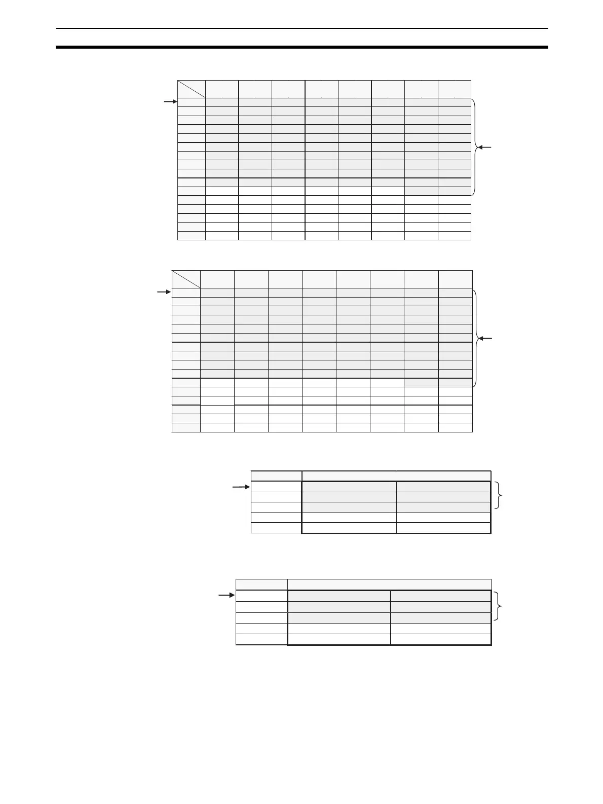
■ Bit Slave Output Area (BIT OUT)
■ Bit Slave Input Area (BIT IN)
■ Word Slave Participation Flags, and Communications Error Flags (Status)
■ Bit Slave Participation Flags and Communications Error Flags (Bit Status)
5-2-5 Status Area Allocation
The Status Area consists of the following three items.
• Status: The status of the network and of the Master Unit
• Parameters: Remote I/O Communications Startup Switches
15 14 13 12 11 10 9 8 7 6 5 4 3 2 1 0
+0 [ BIT IN 7] [ BIT IN 6] [ BIT IN 5] [ BIT IN 4] [ BIT IN 3] [ BIT IN 2] [ BIT IN 1] [ BIT IN 0]
+1 [BIT IN 15] [ BIT IN 14] [ BIT IN 13] [ BIT IN 12] [ BIT IN 11] [ BIT IN 10] [ BIT IN 9] [ BIT IN 8]
+2 [BIT IN 23] [ BIT IN 22] [ BIT IN 21] [ BIT IN 20] [ BIT IN 19] [ BIT IN 18] [ BIT IN 17] [ BIT IN 16]
+3 [ BIT IN 31] [ BIT IN 30] [ BIT IN 29] [ BIT IN 28] [ BIT IN 27] [ BIT IN 26] [ BIT IN 25] [ BIT IN 24]
+4 [ BIT IN 39] [ BIT IN 38] [ BIT IN 37] [ BIT IN 36] [ BIT IN 35] [ BIT IN 34] [ BIT IN 33] [ BIT IN 32]
+5 [ BIT IN 47] [ BIT IN 46] [ BIT IN 45] [ BIT IN 44] [ BIT IN 43] [ BIT IN 42] [ BIT IN 41] [ BIT IN 40]
+6 [ BIT IN 55] [ BIT IN 54] [ BIT IN 53] [ BIT IN 52] [ BIT IN 51] [ BIT IN 50] [ BIT IN 49] [ BIT IN 48]
+7 [ BIT IN 63] [ BIT IN 62] [ BIT IN 61] [ BIT IN 60] [ BIT IN 59] [ BIT IN 58] [ BIT IN 57] [ BIT IN 56]
+8 [ BIT IN 71] [ BIT IN 70] [ BIT IN 69] [ BIT IN 68] [ BIT IN 67] [ BIT IN 66] [ BIT IN 65] [ BIT IN 64]
+9 [ BIT IN 79] [ BIT IN 78] [ BIT IN 77] [ BIT IN 76] [ BIT IN 75] [ BIT IN 74] [ BIT IN 73] [ BIT IN 72]
+10 [ BIT IN 81] [ BIT IN 80]
+11
+12
+13
+14
+15
The first
address is
specified.
Word
address
Bit
Example: When
82 is specified
as the number
of nodes N
Not allocated.
Not allocated.
Not allocated.
Not allocated.
Not allocated.
Not allocated.
Not allocated.
Not allocated.
Not allocated.
Not allocated.
Not allocated.
Not allocated.
Not allocated.
Not allocated.
Not allocated.
Not allocated.
Not allocated.
Not allocated.
Not allocated.
Not allocated.
Not allocated.
Not allocated.
Not allocated.
Not allocated.
Not allocated.
Not allocated.
Not allocated.
Not allocated.
Not allocated.
Not allocated.
Not allocated.
Not allocated.
Not allocated.
Not allocated.
Not allocated.
Not allocated.
Not allocated.
Not allocated.
Not allocated.
Not allocated.
Not allocated.
Not allocated.
Not allocated.
Not allocated.
Not allocated.
Not allocated.
15 14 13 12 11 10 9 8 7 6 5 4 3 2 1 0
+0 [ BIT OUT 7] [ BIT OUT 6] [ BIT OUT 5] [ BIT OUT 4] [ BIT OUT 3] [ BIT OUT 2] [ BIT OUT 1] [ BIT OUT 0]
+1 [ BIT OUT 15] [ BIT OUT 14] [ BIT OUT 13] [ BIT OUT 12] [ BIT OUT 11] [ BIT OUT 10] [ BIT OUT 9] [ BIT OUT 8]
+2 [ BIT OUT 23] [ BIT OUT 22] [ BIT OUT 21] [ BIT OUT 20] [ BIT OUT 19] [ BIT OUT 18] [ BIT OUT 17] [ BIT OUT 16]
+3 [ BIT OUT 31] [ BIT OUT 30] [ BIT OUT 29] [ BIT OUT 28] [ BIT OUT 27] [ BIT OUT 26] [ BIT OUT 25] [ BIT OUT 24]
+4 [ BIT OUT 39] [ BIT OUT 38] [ BIT OUT 37] [ BIT OUT 36] [ BIT OUT 35] [ BIT OUT 34] [ BIT OUT 33] [ BIT OUT 32]
+5 [ BIT OUT 47] [ BIT OUT 46] [ BIT OUT 45] [ BIT OUT 44] [ BIT OUT 43] [ BIT OUT 42] [ BIT OUT 41] [ BIT OUT 40]
+6 [ BIT OUT 55] [ BIT OUT 54] [ BIT OUT 53] [ BIT OUT 52] [ BIT OUT 51] [ BIT OUT 50] [ BIT OUT 49] [ BIT OUT 48]
+7 [ BIT OUT 63] [ BIT OUT 62] [ BIT OUT 61] [ BIT OUT 60] [ BIT OUT 59] [ BIT OUT 58] [ BIT OUT 57] [ BIT OUT 56]
+8 [ BIT OUT 71] [ BIT OUT 70] [ BIT OUT 69] [ BIT OUT 68] [ BIT OUT 67] [ BIT OUT 66] [ BIT OUT 65] [ BIT OUT 64]
+9 [ BIT OUT 79] [ BIT OUT 78] [ BIT OUT 77] [ BIT OUT 76] [ BIT OUT 75] [ BIT OUT 74] [ BIT OUT 73] [ BIT OUT 72]
+10 [ BIT OUT 81] [ BIT OUT 80]
+11
+12
+13
+14
+15
The first
address is
specified.
Word
address
Bit
Example: When
82 is specified
as the number
of nodes N
Not allocated.
Not allocated.
Not allocated.
Not allocated.
Not allocated.
Not allocated.
Not allocated.
Not allocated.
Not allocated.
Not allocated.
Not allocated.
Not allocated.
Not allocated.
Not allocated.
Not allocated.
Not allocated.
Not allocated.
Not allocated.
Not allocated.
Not allocated.
Not allocated.
Not allocated.
Not allocated.
Not allocated.
Not allocated.
Not allocated.
Not allocated.
Not allocated.
Not allocated.
Not allocated.
Not allocated.
Not allocated.
Not allocated.
Not allocated.
Not allocated.
Not allocated.
Not allocated.
Not allocated.
Not allocated.
Not allocated.
Not allocated.
Not allocated.
Not allocated.
Not allocated.
Not allocated.
Not allocated.
+0
+1
: : :
+14
+15
The first
address is
specified.
Word address Bit 15 Bit 0
Communications Error Flags: OUT0 to OUT7
Participation Flags: OUT0 to OUT7
The number
of nodes N
is specified.
Communications Error Flags: IN0 to IN7
Communications Error Flags: OUT56 to OUT63
Communications Error Flags: IN56 to IN63
Participation Flags: IN0 to IN7
Participation Flags: OUT56 to OUT63
Participation Flags: IN56 to IN63
+0
+1
: : :
+30
+31
The first
address is
specified.
Word address
Bit 15 Bit 0
Communications Error Flags: BIT OUT0 to BIT OUT7
Participation Flags: BIT OUT0 to BIT OUT7
The number
of nodes N
is specified.
Communications Error Flags: BIT IN0 to BIT IN7
Communications Error Flags: BIT OUT 120 to BIT OUT 127
Communications Error Flags: BIT IN 120 to BIT IN 127
Participation Flags: BIT IN0 to BIT IN7
Participation Flags: BIT OUT 120 to BIT OUT 127
Participation Flags: BIT IN 120 to BIT IN 127