128
Allocations to Slave Units Section 5-2
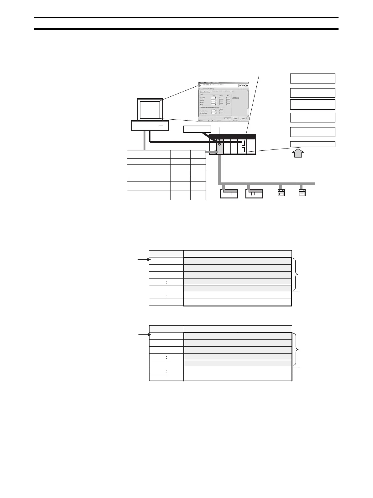
In the Software Setting Mode, memory is allocated to each Word Unit and Bit
Unit for the Word IN/OUT Areas, Bit IN/OUT Areas, Participation Flags, and
Communications Error Flags.
Refer to the SYSMAC CS/CJ/CP/NSJ Series CX-Integrator Version 2.3 Oper-
ation Manual (Cat. No. W464) for the editing procedures for software setting
tables.
■ Word Slave Output Area (OUT)
■ Word Slave Input Area (IN)
CX-Integrator
Word Slaves
CompoNet
Bit Slaves
CompoNet Master Unit
CS/CJ-series PLC
The addresses and areas for the Word OUT
Area, Word IN Area, Bit OUT Area, Bit IN Area,
Participation Flags, and Communications Error
Flags are set for each Word Unit and Bit Unit.
Software Setting Table
Area
Word OUT
Word IN
Bit OUT
Bit IN
I/O memory
Mode No. = 8
Word IN Area
Word OUT Area
Word Unit Participation
Status
Bit IN Area
Bit OUT area
Bit Partici
ation Status
User-set location
User-set location
User-set location
User-set location
User-set location
User-set location
:
:
Participation/Communications
Error Flags: Word Units
Participation/Communications
Error Flags: Bit Units
Start
area/address
Number
of nodes
+0 [ OUT0 ]
+1 [ OUT1 ]
+2 [ OUT2 ]
:
+N-1 [ OUT ( N-1 ) ]
+63
The first
address is
specified.
Word address Bit 15
Bit 0
The number of
nodes address
areas is specified.
Not allocated.
Not allocated.
+0 [ IN0 ]
+1 [ IN1 ]
+2 [ IN2 ]
:
+N-1 [ IN ( N-1 ) ]
+63
The first
address is
specified.
Word address Bit 15
Bit 0
The number of
nodes address
areas is specified.
Not allocated.
Not allocated.