13
Devices in a CompoNet Network Section 1-3
Note (1) In a CompoNet Network, Word Slave Units have 16 bits per node ad-
dress. Bit Slave Units have two bits allocated per node address.
(2) Do not use the reserved communications mode numbers (4 to 7 and 9).
A communications mode setting error (H4 at the 7-segment LED indica-
tor) will occur if any of these mode numbers is set.
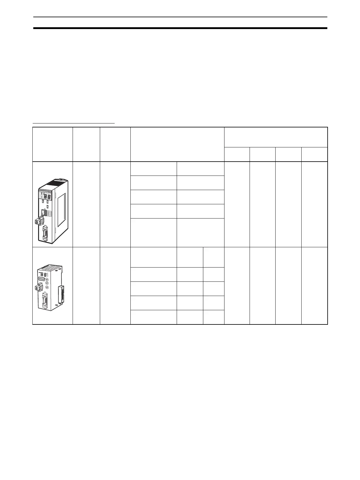
1-3 Devices in a CompoNet Network
1-3-1 Master Units
CompoNet Master Units
Note (1) A DCN4-TB4 Open Type Connector is required to connect a Round Cable
I or Round Cable II cable to the Unit.
(2) A DCN4-TR4 Flat Connector Socket is required to connect a Flat Cable I
cable.
(3) A DCN5-TR4 Flat Connector Socket is required to connect a Flat Cable
II cable.
Name Model
Unit
classifica-
tion
Maximum number per CPU Unit
Communications Cables
(Yes: Can be used. No: Cannot be
used.)
Round
Cable I
Round
Cable II
Flat
Cable I
Flat
Cable II
CS-series
Master Unit
CS1W-
CRM21
CS-series
Special I/O
Unit
Communications
mode No.
Ye s ( S e e
note 1.)
Yes (See
note 1.)
Ye s ( S e e
note 2.)
Ye s ( S e e
note 3.)
8 (1 unit number
used)
80
0 (2 unit num-
bers used)
48
1 (4 unit num-
bers used)
24
2 or 3 (8 unit
numbers used)
12
CJ-series
Master Unit
CJ1W-
CRM21
CJ-series
Special
Communications
mode No.
CJ1-H/
CJ1 CPU
Units
CJ1M
CPU
Units
Ye s ( S e e
note 1.)
Yes (See
note 1.)
Ye s ( S e e
note 2.)
Ye s ( S e e
note 3.)
8 (1 unit number
used)
40 20
0 (2 unit num-
bers used)
40 20
1 (4 unit num-
bers used)
24 20
2 or 3 (8 unit
numbers used)
12 12
C
R
M
2
1
MS
NS
S
D
R
D
+
1
0
0
M
A
C
H
N
o
.
X
1
0
1
M
O
D
E
ON
X
1
0
0
1234
1
D
R
0
2
D
R
1
3
E
S
T
P
4
REGS
N
E
T
W
O
R
K
P
O
W
E
R
S
U
P
P
L
Y
D
C
2
4
V
I
N
P
U
T
B
S
+
B
S
+
B
D
H
B
D
L
B
S
-
B
S
-
C
R
M
2
1
+
1
0
0
M
S
N
S
SD
RD
MACH
No.
MODE
X
1
0
1
O
N
X
1
0
0
B
S
+
B
S
-
D
C
2
4
V
I
N
P
U
T
B
S
+
B
D
H
D
B
L
B
S
-
SW
1234
1
2
3
4
0
1
2
3
4
5
6
7
8
9
0
1
2
3
4
5
6
7
8
9
0
1
2
3
4
5
6
7
8
9
N
E
T
W
O
R
K
P
S