40
Master Unit Specifications Section 2-1
DIP Switch This setting is read when the power supply is turned ON to the PLC.
Baud Rate Setting
Slave Units automatically detect the baud rate set on SW1 (DR0) and SW2
(DR2). It is not necessary to set the baud rate separately for any of the Slave
Units.
Communications Error
Communications Stop
Mode Setting
When SW3 (ESTP) is turned ON, all remote I/O communications are stopped
when a communications error occurs at any Slave Unit. (The Communications
Error Communications Stop Flag at status bit 02 also turns ON.) When SW3
is turned OFF, remote I/O communications continue even if a communications
error occurs at a Slave Unit.
Registration Table Enable
Setting
If the power is turned ON while SW 4 (REGS) is ON, the registration tables
that have been edited or downloaded by the CX-Integrator will be enabled.
Only registered Slave Units can participate. The registered Slave Units are
also compared to actual Slave Units. If they do not agree, the Registered
Table Verification Error Flag in status bit 01 will turn ON.
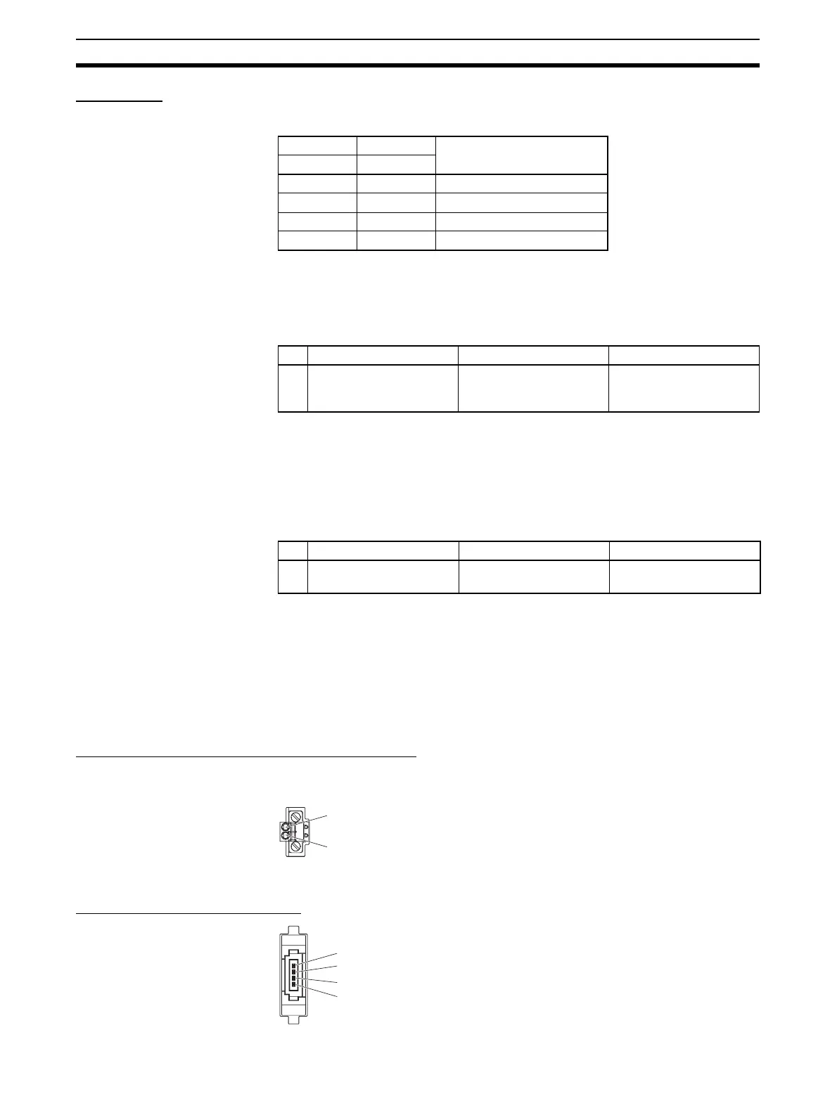
2-1-5 Terminal Arrangement
Communications Power Supply Connector
This connector supplies communications power to Slave Units and Repeater
Units connected to the trunk line.
Note This connector does not supply power to the Master Unit.
Communications Connector
SW1 SW2 Baud rate setting
DR0 DR1
OFF OFF 4 Mbps (default)
ON OFF 3 Mbps
OFF ON 1.5 Mbps
ON ON 93.75 kbps
SW Name ON OFF
3 ESTP (Communications
Error Communications
Stop Mode)
Communications stop
when a communications
error occurs.
Communications do not
stop when a communica-
tions error occurs.
SW Name ON OFF
4 REGS (Registration
Table Enable Setting)
Registration Table
enabled.
Registration Table dis-
abled.
BS+ (communications power supply positive side)
BS− (communications power supply negative side)
BS+ (communications power supply positive side)
BDH (communications data high side)
BDL (communications data low side)
BS− (communications power supply negative side)