58
CompoNet Network Wiring Section 3-2
3-2-10 Connection Locations for Communications Power Supply
Connect the communications power supply as shown in the following dia-
grams.
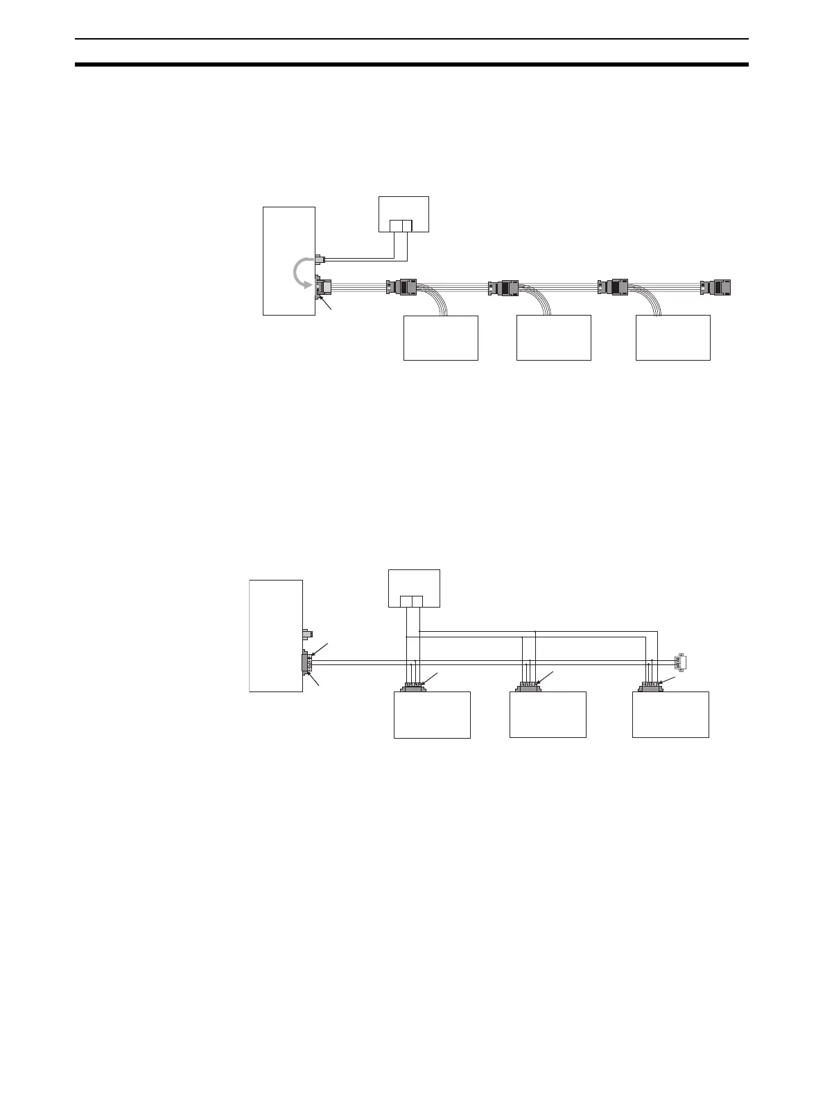
Round Cable II, Flat Cable
I, or Flat Cable II
Example for Flat Cable I or II
The communications power supply (BS+ and BS-) is connected to the com-
munications power supply connector on the Master Unit. Doing so will supply
communications power to the Slave Units on the trunk line from the Round
Cable II, Flat Cable I, or Flat Cable II.
Note (1) Connect the communications power supply at only one location for the
trunk line and each sub-trunk line.
(2) Connect the communications power supply to the downstream port com-
munications power supply connector on the Repeater Unit to supply pow-
er to a sub-trunk line.
Round Cable I
The communications power supply (BS+ and BS-) is connected separately to
each Slave Unit and Repeater Unit (see note). Power does not need to be
supplied to the Master Unit.
Note The communications power to the Repeater Unit must be supplied
to the BS+ and BS- terminals on the upstream port (port 1).
Refer to 4-4 Power Supply Wiring for details on wiring the communications
power supply.
+−
Master Unit
Com-
muni-
cati-
ons
power
supply
Communica-
tions power
supply, 24 VDC
Communications
connector
Flat Cable I or II
Slave Unit
Terminating Resistor
Slave Unit
Slave Unit
+−
Master Unit
Open Type Connector
Round Cable I
Communications connector
Communica-
tions power
supply, 24 VDC
Supply communications power directly to each Slave Unit.
Normal Slave Unit
Terminating Resistor
Open Type Connector
Open Type Connector
Open Type Connector
Normal Slave Unit
Normal Slave Unit