35
Master Unit Specifications Section 2-1
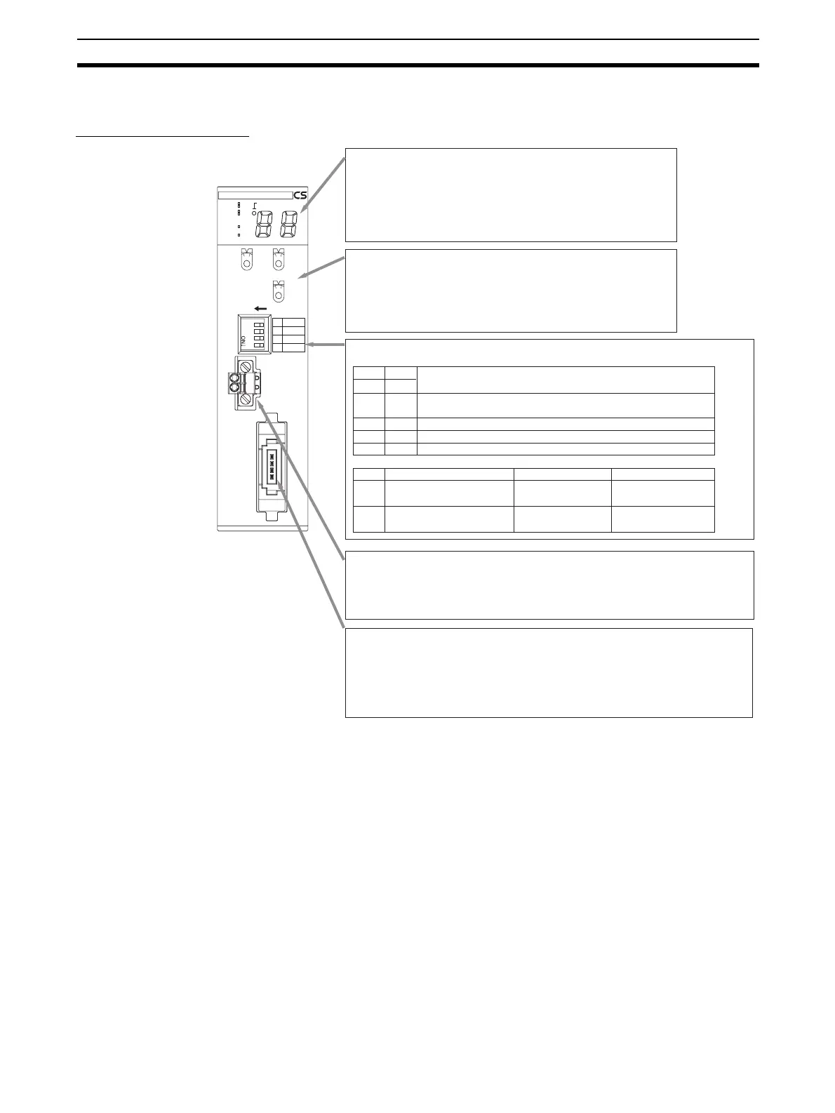
2-1-2 Component Names and Functions
CS-series Master Unit
CRM21
MS
NS
SD
RD
+100
MACH
No.
X10
1
MODE
ON
X10
0
1234
1
DR0
2
DR1
3
ESTP
4
REGS
NETWORK
POWER
SUPPLY
DC24V
INPUT
BS+
BS
+
BD H
BD L
BS
-
BS
-
SW1 SW2
DR0 DR1
OFF OFF
ON OFF
OFF ON
ON ON
SW Name ON OFF
3
4
Display Section
Shows the Master Unit status and Slave Unit communications status.
· Indicators
Four LED indicators:
MS (green/red), NS (green/red), SD (yellow), and RD (yellow)
· Seven-segment Display
Displays the communications status, error code, etc.
(two digits plus a dot that indicates "+100")
Rotary Switches
· MACH No.
Special I/O Unit unit number setting
Two decimal rotary switches (0 to 99)
· MODE
Communications mode number of the Master Unit
One decimal rotary switch (0 to 9)
DIP Switch
Used to set the baud rate, communications stop mode, and Registration Table (4-pin switch).
Baud rate setting
4 Mbits/s (default)
Note: A baud rate of 4 Mbits/s is not supported for branch lines and thus cannot be used for
Slave Units with Cables (i.e., Bit Slave Units).
Communications Power Supply Connector
Connect this connector to a 24-VDC power supply when using Round Cable II, Flat Cable
I, or Flat Cable II cable.
Doing so will supply communications power to the Slave Units and Repeater Units on the
trunk line from the communications connector through the Flat Cable.
Note: Do not connect anything to this connector when using Round Cable I cable.
Communications Connector
Connect the communications cable to this connector.
BS+, BS- (communications power) and BDH, BDL (communications data)
BS+ and BS- are used only when using Round Cable II, Flat Cable I, or Flat Cable II
cable to output the communications power supply connected to the communications
power supply connector.
Note: Open Type Connector (to connect Units to the Cable) can be used to connect to a
terminal block.
3 Mbits/s
1.5 Mbits/s
93.75 kbits/s
ESTP (Communications Error
Communications Stop Mode)
Communications stop
when a communications
error occurs.
Communications do not
stop when a communica-
tions error occurs.
REGS (Registration Table
Enable Setting)
Registration Table
enabled.
Registration Table
disabled.