105
Exchanging Data with the CPU Unit Section 5-1
Note If there are no Slave Unit inputs for node address N+1, there will be
no node address duplication error for node address N+1. If there
are Slave Unit inputs for node address N+1, a node address dupli-
cation error will occur.
If 16 Slave Unit outputs at node address N are expanded by 8 outputs to
make a total of 24 outputs, then Output Area node address N and node ad-
dress N+1 are allocated.
Note If there are no Slave Unit outputs for node address N+1, there will
be no node address duplication error for that N+1. If there are Slave
Unit outputs for node address N+1, a node address duplication er-
ror will occur.
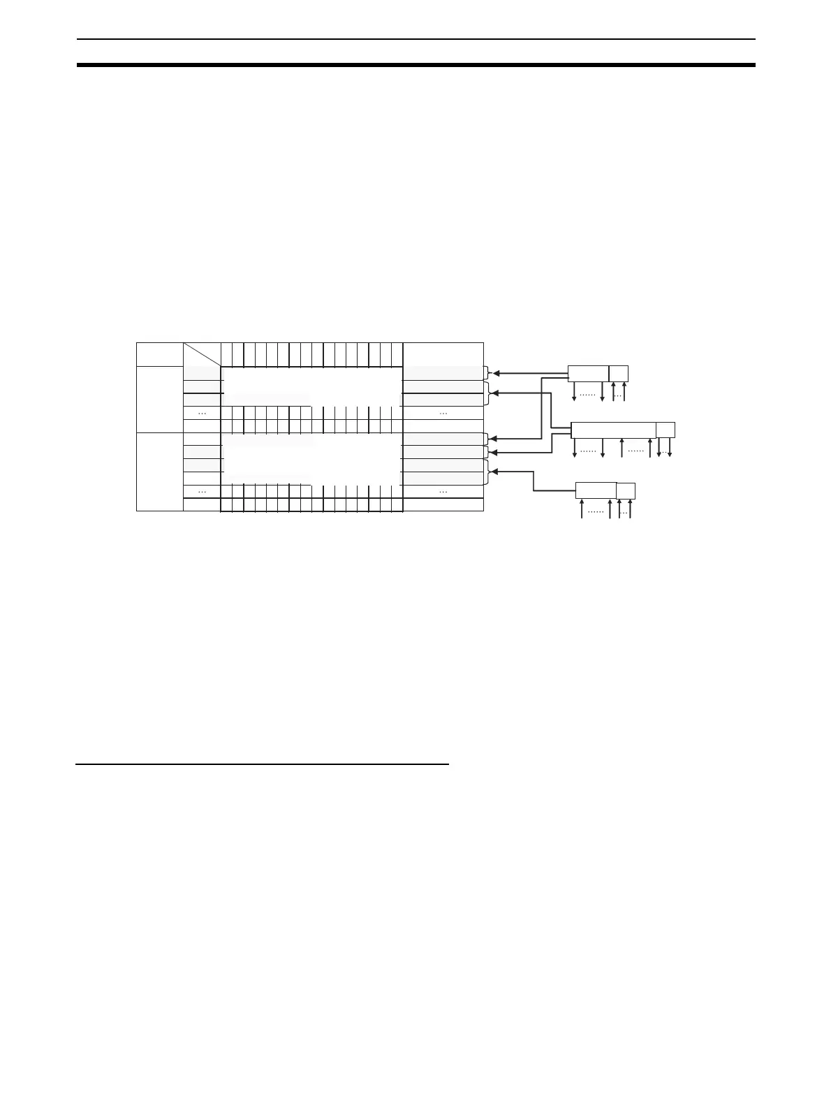
Allocation Example
Note (1) The 8 expansion inputs for node address 0 are allocated bits 00 to 07 of
CIO 2008 for node address 0. (Bits 08 to 15 are not used.)
(2) The 8 expansion outputs for node address 1 are allocated bits 00 to 07 of
CIO 2002 for node address 2, following node address 1. (Bits 08 to 15 of
CIO 2002 are not used.)
(3) The 8 expansion inputs for node address 2 are allocated bits 00 to 07 of
CIO 2011 for node address 3, following node address 2. (Bits 08 to 15 of
word 2011 are not used.)
5-1-5 Slave Unit Normal Confirmation
Participation and Communications Error Flags
• Participation Flags and Communications Error Flags in the Status Area
are used to indicate whether Slave Units are participating normally in the
network.
• Participation Flags
A Participation Flag turns ON once the corresponding Slave Unit starts
participating in the network when the System is started (i.e., when the
power is turned ON). It remains ON even if the Slave Unit stops partic-
ipating due to a communications error.
15 11 10 9 8 7 6 54321 0
Output
Area
Input
Area
Bit
Address
CIO 2000
Example for Mode 0
I/O Memory (Allocated in the Special I/O Unit Area in the CIO Area)
CIO 2001
CIO 2007
CIO 2008
CIO 2009
CIO 2010
CIO 2015
Node address 0 outputs 0 to 15 are allocated bits 0 to 15.
Node address 1 outputs 0 to 15 are allocated bits 0 to 15.
16 outputs
16 outputs
Slave Unit
Slave Unit
Slave Unit
Node address 0 (Output 0 and input 0 allocated)
Input allocations
Input allocations
Output allocations
Output
allocations
Node address
For node address 3
For node address 7
For node address 0
For node address 1
For node address 7
For node address 2
CIO 2002
CIO 2011
Bits 8 to 15 are not used. Node address 1 expansion outputs 0
to 7 are allocated bits 0 to 7. (See note 2.)
Bits 8 to 15 are not used. Node address 0 expansion outputs 0
to 7 are allocated bits 0 to 7. (See note 1.)
Bits 8 to 15 are not used. Node address 0 expansion outputs 0
to 7 are allocated bits 0 to 7. (See note 3.)
Node address 1 outputs 0 to 15 are allocated bits 0 to 15.
Node address 2 outputs 0 to 15 are allocated bits 0 to 15.
For node address 0
For node address 1
For node address 2
Input allocations
Expan-
sion Unit
16 outputs
8 inputs (See note 1.)
Node address 1 (Outputs 1 and 2 and input 1 allocated)
16 inputs and 8 outputs (See note 2.)
Node address 2 (Inputs 2 and 3 allocated)
8 inputs (See note 3.)
Output/
input
14 13 12
Expan-
sion Unit
Expan-
sion Unit