104
Exchanging Data with the CPU Unit Section 5-1
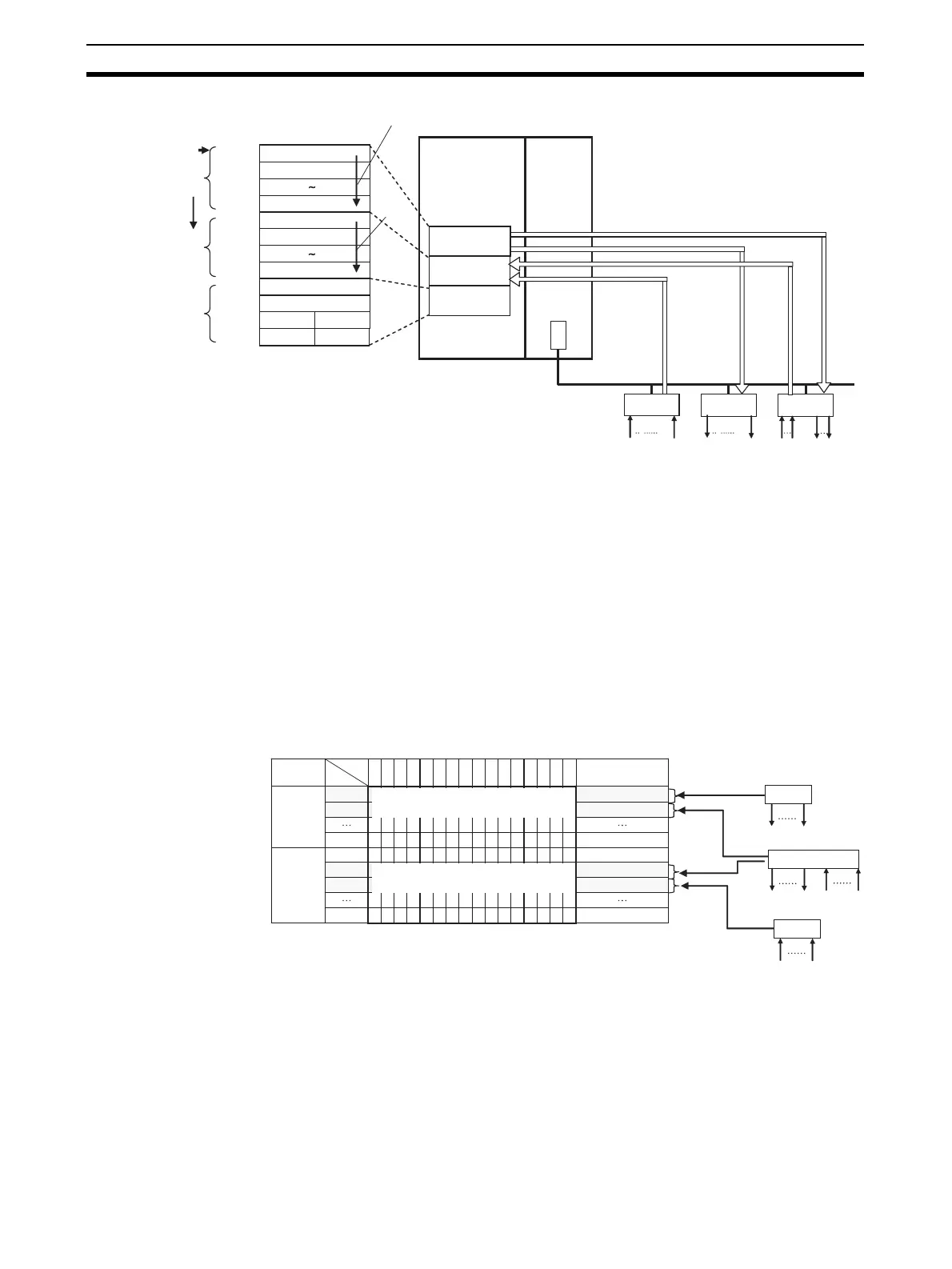
• The Input Area is allocated to Input Slave Units, the Output Area is allo-
cated to Output Slave Units, and both the Input Area and the Output Area
are allocated to Mixed I/O Slave Units.
The 16 Slave Unit inputs for node address N are allocated in one word (bits
00 to 15) at node address N in the Input Area.
The 16 Slave Unit outputs for node address N are allocated in one word
(bits 00 to 15) at node address N in the Output Area.
The 16 Slave Unit inputs and 16 Slave Unit outputs for node address N are
allocated in one word (bits 00 to 15) plus one word (bits 00 to 15) at node
address N in the Input Area and node address N in the Output Area.
Allocation Example
• For node requiring only 8 inputs or 8 outputs, the node is allocated the
rightmost byte of the respective word (bits 00 to 07). The leftmost byte
(bits 08 to 15) is not used.
• If there are more than 16 Slave Unit inputs or outputs, both the node
address and the next node address (+1) are allocated.
If 16 Slave Unit inputs at node address N are expanded by 8 inputs to make
a total of 24 inputs, then Input Area node address N and node address N+1
are allocated.
CPU Unit
Inputs
Outputs
Inputs
Outputs
15
8
7
0
CIO 2000
CIO 2001
CIO 2007
CIO 2008
CIO 2009
CIO 2015
CIO 2016
CIO 2017
CIO 2018
CIO 2019
Example for Mode 0
Word address
First address
Output Area
Order:
Outputs,
then inputs
Input Area
Status Area
Node address 0
Node address 1
Status
Setting parameter
Node address 7
Node address 0
Node address 1
Node address 7
Output communi-
cations error
Input communi-
cations error
Node address order
I/O Memory (Special
I/O Unit Area in the
CIO Area)
Output Area
Input Area
Status Area
Node
address
order
CompoNet Master Unit
Mode 0
(Rotary switch)
Remote I/O communications
Outputs
Inputs
CompoNet Network
Output slave unit
participation
Input slave unit
participation
Input Slave
Unit
Output Slave
Unit
I/O Slave
Unit
Bit
Address
15 14 13 12 11 10 9 8 7 6 5 4 3 2 1 0
CIO 2000
Output
Area
Input
Area
Example for Mode 0
I/O Memory (Allocated in the Special I/O Unit Area in the CIO Area)
CIO 2001
CIO 2007
CIO 2008
CIO 2009
CIO 2010
CIO 2015
Node address 0 outputs 0 to 15 are allocated bits 0 to 15.
Node address 1 outputs 0 to 15 are allocated bits 0 to 15.
Node address 1 outputs 0 to 15 are allocated bits 0 to 15.
Node address 2 outputs 0 to 15 are allocated bits 0 to 15.
16 in
uts
16 input
16 outputs
16 outputs
Slave Unit
Slave Unit
Slave Unit
Node address 0
Node address 1
Node address 2
Input allocations
Input allocations
Output allocations
Output allocations
Node address
For node address 0
For node address 1
For node address 7
For node address 0
For node address 1
For node address 7
For node address 2
Output/
input