4
CompoNet Networks Section 1-1
• Sub-branch line: The transmission path created using a T-branch from a
branch line. (T-branching is not possible from sub-branch lines.)
Note Due to differences in functionality, the same type of cable must be
used between the trunk line and a branch line, a sub-trunk line and
a branch line, and a branch line and a sub-branch line. Different
types of cable can be used between the trunk line and a sub-trunk
line.
Branches There are two ways to create branch lines.
1) T-branch Connections
• T-branch connections using Flat Connectors (when Flat Cable I or Flat
Cable II is used)
• T-branch connections using commercially available relay terminals (when
round cable I or round cable II is used)
2) Multidrop Connections
• Multidrop connections using Flat Connectors and Multidrop Connectors
(when Flat Cable I or Flat Cable II is used)
• Multidrop connections using Open Type Connectors (when round cable I
or round cable II is used)
Note Flat Connectors can also be used to extend the Communications
Cable.
Communications Power
Supply
This is the power supply for communications and internal operations for each
Unit.
A commercially available 24-VDC power supply is used for communications
and internal operations in each Unit.
One communications power supply can be connected for a trunk line or a sub-
trunk line. Communications power is supplied to the trunk line from the Master
Unit and to a sub-trunk line from the Repeater Unit.
One power supply cannot be used to supply communications power to more
than one line (i.e., to the trunk line and sub-trunk line or to two sub-trunk
lines).
I/O Power Supply A commercially available 24-VDC power supply is used to power the I/O oper-
ations of the external I/O device connected to a Unit. It is connected to the I/O
power supply terminal of the Unit.
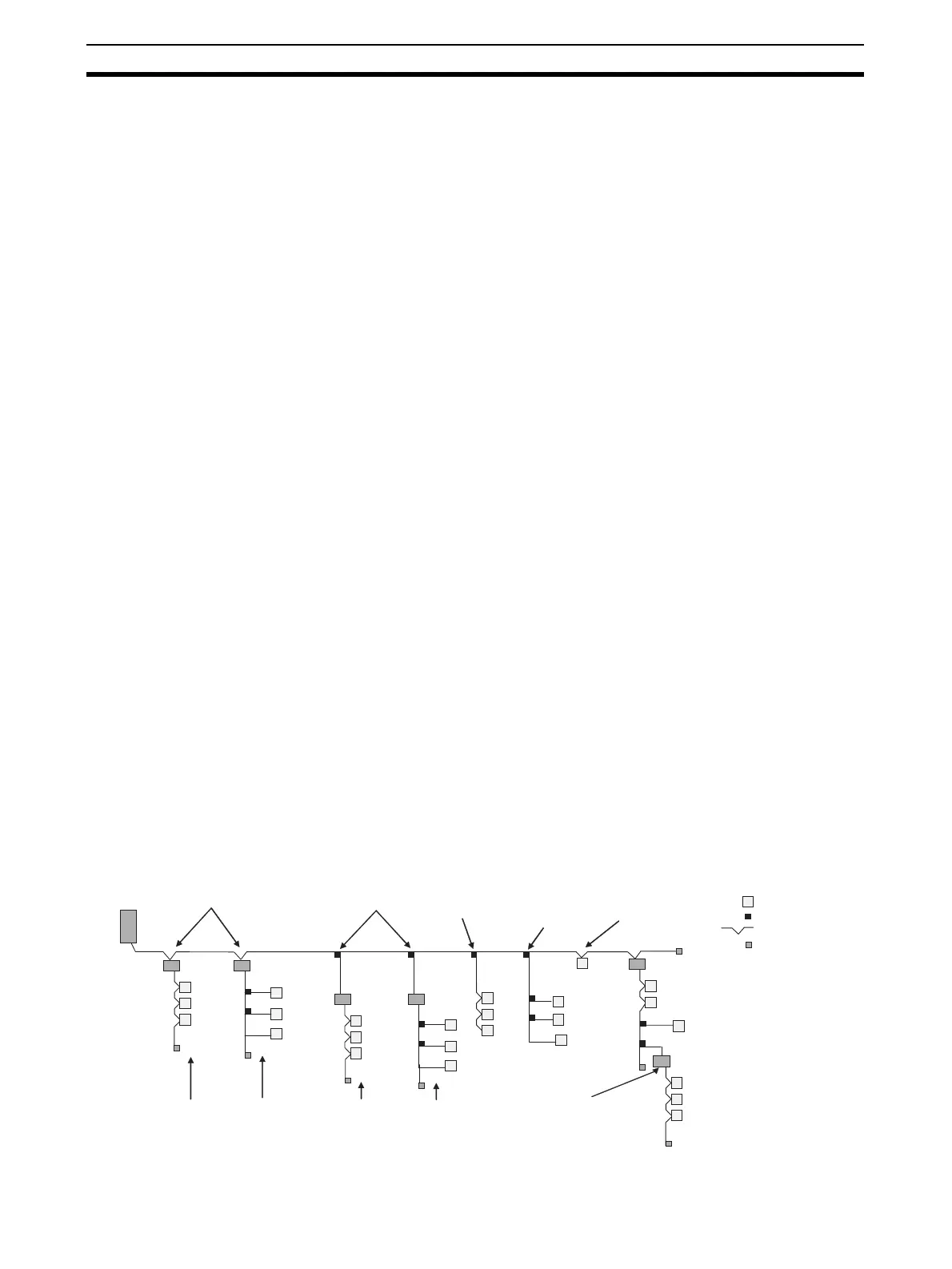
1-1-3 System Configuration Patterns
: Terminating Resistor
Repeater Units connected
with multidrop connections
Master
Unit
Repeater
Unit
Repeater
Unit
Repeater
Unit
Repeater
Unit
Repeater Unit
Repeater Unit
Sub-trunk
line
Sub-branch line
Slave Units
Slave Units
Slave Units
Slave Units
Slave Units
Slave Units
Slave Units
Slave Units connected
with multidrop
connections
Branch line
Branch line Branch line Branch line
Branch line
Branch line
Slave
Unit
: Slave Unit
Trunk line
Slave Units
connected with T-
branch
connections
Repeater Units connected
with T-branch connections
Slave Units
connected with
multidrop
connections
Slave Units connected
with T-branch
connections
Slave Units connected
with T-branch and then
multidrop connections
: T-branch
Branch line
Branch line
Slave Units connected
with T-branch and
then T-branch
connections
Slave Units
connected with
multidrop
connections
Terminating
Resistor
Repeater Unit
connected to
create second
segment layer
: Multidrop
Sub-trunk
line
Sub-trunk
line
Sub-trunk
line
Sub-trunk
line
Sub-trunk
line