99
Power Supply Wiring Section 4-4
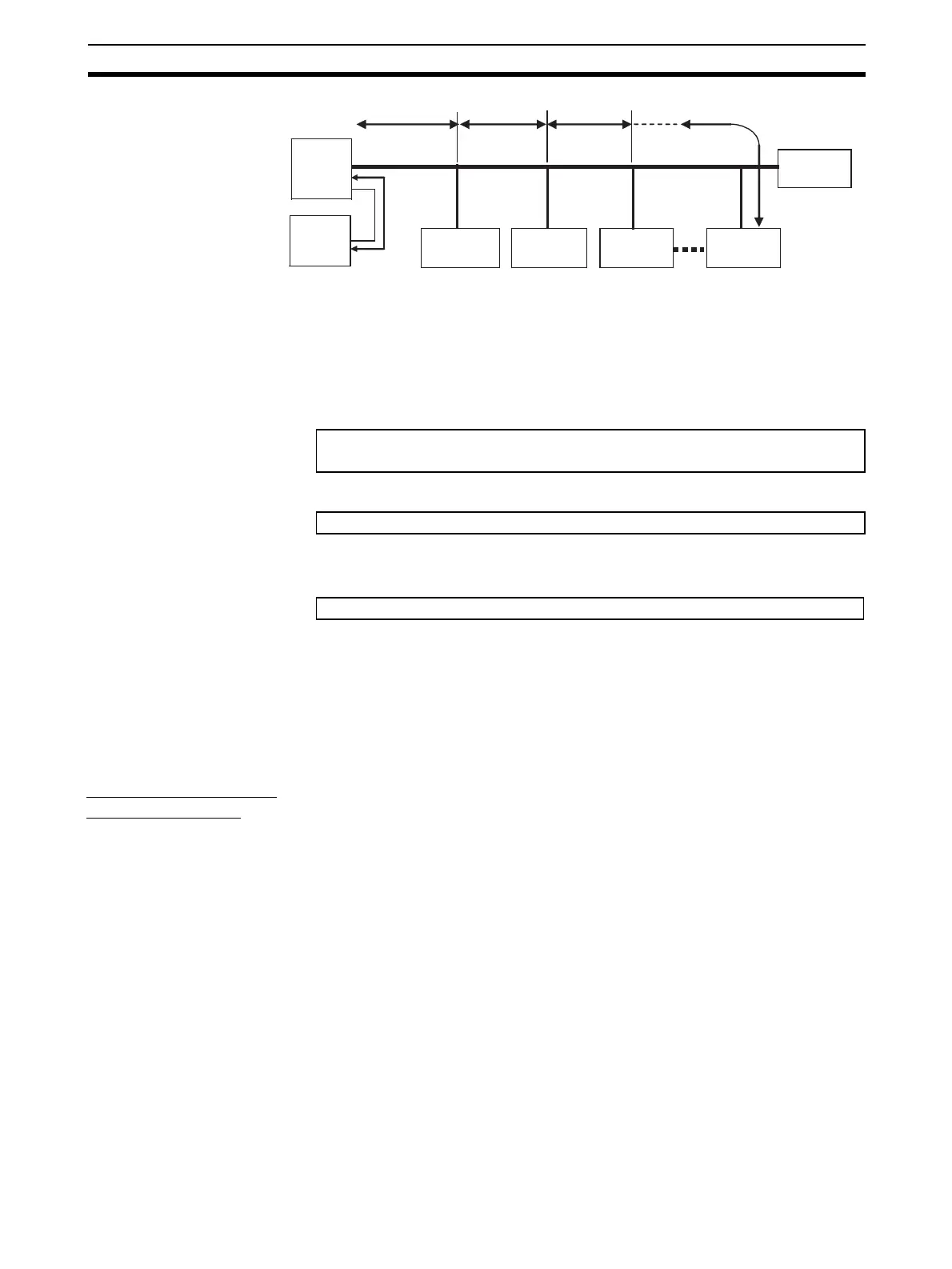
■ Calculation Example
The allowable power supply voltage range for Slave Units is 14 to 26.4 VDC. If
a 24-VDC power supply is used, the allowable voltage drop is 10 V.
The relationship between the cable and the length that can be extended is
expressed by the following formula:
To provide leeway when selecting the cable, use the following approximation.
R = Cable conductor resistance = 0.025 W/m for Flat Cable
The extended length of the cable is thus expressed by the following formula:
4-4-6 Precautions on Locating the I/O Power Supply
When building a system, the supply methods for communications power and I/
O power must be considered. Not only hardware, such as selecting the power
supplies and cables based on allowable currents and voltage drop, be consid-
ered, but also system operation for power supply errors, costs, and other soft-
ware issues must be considered when studying power supply methods.
Supplying I/O Power
from One Source
When supplying I/O power to the entire system from one source, the power
consumed by each devices and the loads must be considered. Select the
cables so that the power supply voltage for the last Slave Unit and load will be
within the allowable range.
Also, give proper consideration to the power supply capacity and be sure the
total line current is within the allowable current range of the cable.
The following measures can be considered to keep the voltage drop within the
allowable range when supplying power from one power supply.
• Increase the thickness of the cables.
• Increase the output voltage of the power supply.
• Shorting the wiring.
• Locate the power supply in the middle of the network.
L1
L3
L2 Ln
3 m max.
Master
Unit
Power
supply,
24 VDC
Slave Unit
current con-
sumption I
1
Terminating
Resistor
Slave Unit
current con-
sumption I
2
Slave Unit
current con-
sumption I
3
Slave Unit
current con-
sumption I
n
10 (V) ≥ {(I
1
+ I
2
+ I
3
+ … + I
n
) × R
1
× L
1
× 2} + {(I
2
+ I
3
+ … + In) × R
2
× L
2
× 2} + {(I
3
+ … + I
n
) × R
3
× L
3
× 2} + … + {I
n
× R
n
× L
n
× 2}
10(V) ≥ {(I1 + I2 + I3 + … + In) × R × L × 2}
L (m) ≤ 200 ÷ (I1 + I2 + I3 + … + In) … For Flat Cable