7
CompoNet Network Specifications Section 1-2
■ Communications Error Input Data Zero Clear Mode
Input Data Zero Clear Mode can be set from the CX-Integrator for communi-
cations error. If a communications error occurs for a Slave Unit in this mode,
all input data for that Slave Unit will be cleared to zeros. This can be used to
suppress triggering operations when communications errors have occurred in
systems where ON input data signals are used as triggers for operation.
■ Communications Status on Master Unit Seven-segment Display
The seven-segment display on the front of the Master Unit can be used to
check communications status.
The baud rate is normally displayed, but if an error occurs, the error code is
displayed in hexadecimal and the error node address is displayed in decimal.
Automatic Baud Rate
Detection
The Slave Units will automatically detect and use the baud rate set on the DIP
switch on the Master Unit. Setting the baud rate is not necessary for any of the
Slave Units.
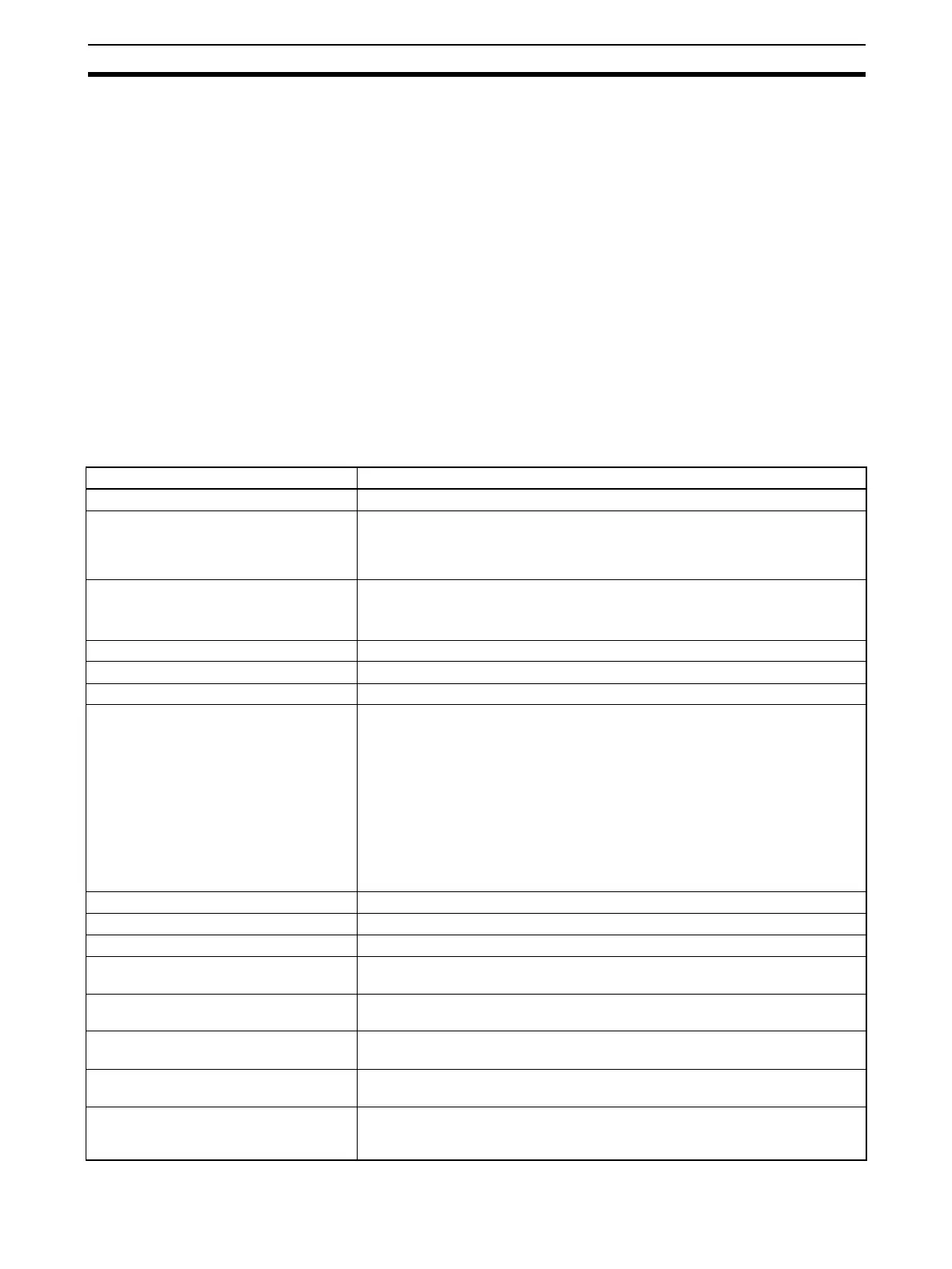
1-2 CompoNet Network Specifications
Item Specifications
Communications method CompoNet protocol
Types of communications Remote I/O communications (programless, constant sharing of data with Slave
Units) and message communications (explicit message communications as
required with Slave Units and FINS message communications as required with
PLCs)
Baud rate 4 Mbps (See note)., 3 Mbps, 1.5 Mbps, 93.75 kbps
Note A baud rate of 4 Mbps is not supported for branch lines and thus cannot
be used for Slave Units with Cables (i.e., Bit Slave Units).
Modulation Base-band
Coding Manchester code
Error control Manchester code rules, CRC
Communications media The following cables can be used.
• Round Cable I (VCTF 2-conductor cable, JIS C3306)
• Round Cable II (VCTF 4-conductor cable, JIS C3306)
• Flat Cable I (DCA4-4F10 Standard Flat Cable)
• Flat Cable II (DCA5-4F10 Sheathed Flat Cable)
Note Round Cable I, Round Cable II, Flat Cable I, and Flat Cable II cables are
all treated as different types of cables. When two or more type of cables
are used in a single network, a Repeater Unit must be used to separate
any two different types of cables between the trunk line and a sub-trunk
line.
Communications distance and wiring Refer to 1-2-1 Cable Types, Maximum Distances, and Number of Slave Units.
Connectable Master Units CompoNet Master Units
Connectable Slave Units CompoNet Slave Units
Maximum I/O capacity Word Slave Units: 1,024 inputs and 1,024 outputs (2,048 I/O points total)
Bit Slave Units: 256 inputs and 256 outputs (512 I/O points total)
Maximum number of nodes Word Slave Units: 64 input nodes and 64 output nodes
Bit Slave Units: 128 input nodes and 128 output nodes
Bits allocated per node address Word Slave Units: 16 bits
Bit Slave Units: 2 bits
Maximum number of nodes per trunk line
or sub-trunk line
32 nodes including Repeater Units
Applicable node addresses Word Slave Units: IN0 to IN63 and OUT0 to OUT63
Bit Slave Units: BIT IN0 to BIT IN127 and BIT OUT0 to OUT127
Repeater Units: 0 to 63