60
Installation Section 4-1
4-1 Installation
Note (1) A sheet is attached to the Master Unit to prevent pieces of wire from en-
tering it. Install and wire the Master Unit with this sheet in place. Stray
strands of wire could cause malfunctions.
(2) Be sure to remove the sheet after installation and wiring to facilitate cool-
ing. The Master Unit could overheat and malfunction if the sheet is not re-
moved.
4-1-1 Tools Required for Installation and Wiring
The following tools are required to install, wire, and set the Units.
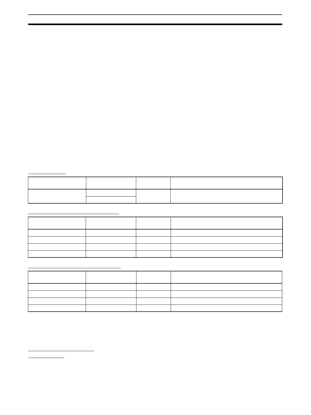
4-1-2 Installation Locations According to Degree of Protection
The degree of protection of the CompoNet Network Units depends on the
model of the Unit. The degree of protection for each Unit is given in the follow-
ing table. Select suitable installation locations accordingly.
Master Units
Flat Cable I Peripheral Devices
Flat Cable II Peripheral Devices
4-1-3 Installing the Master Unit
The Master Unit is installed and used as part of the PLC. The installation
method on the PLC is the same as for any normal Unit.
System Configuration
Precautions
• For a CS-series PLC, the Master Unit can be mounted to a CPU Back-
plane (CS1W-BC@@@) or an Expansion Backplane (CS1W-BI@@@). Up
to 80 Units can be mounted for any one PLC.
• For a CJ-series PLC, the Master Unit can be connected in the CPU Rack
or an Expansion Rack (10 Units per Rack). Up to 40 Units can be
mounted for any one PLC.
• Phillips screwdrivers: M3 and M4: To install and wire I/O for the Master Unit, Slave
Units, and Repeater Units.
• Precision screwdriver: To set rotary switches and DIP switches.
Name Model Degree of
protection
Applicable peripheral devices
Master Units CS1W-CRM21 --- Flat Cable I Peripheral Devices, Flat Cable II Periph-
eral Devices, and Round Cable I
CJ1W-CRM21
Name Model Degree of
protection
Applicable peripheral devices
Flat Cable I DCA4-4F10 --- Flat Cable I (standard, 100 m)
Flat Connector Socket DCN4-TR4 IP40 Required when using Flat Cable I
Flat Connector Plug DCN4-BR4 IP40 Required when using Flat Cable I
Terminating Resistor DCN4-TM4 IP40 Required when using Flat Cable I
Name Model Degree of
protection
Applicable peripheral devices
Flat Cable II DCA5-4F10 --- Flat Cable II (sheathed, 100 m)
Flat Connector Socket DCN5-TR4 IP54 Required when using Flat Cable II
Flat Connector Plug DCN5-BR4 IP54 Required when using Flat Cable II
Terminating Resistor DCN5-TM4 IP54 Required when using Flat Cable II