138
Allocations to Slave Units Section 5-2
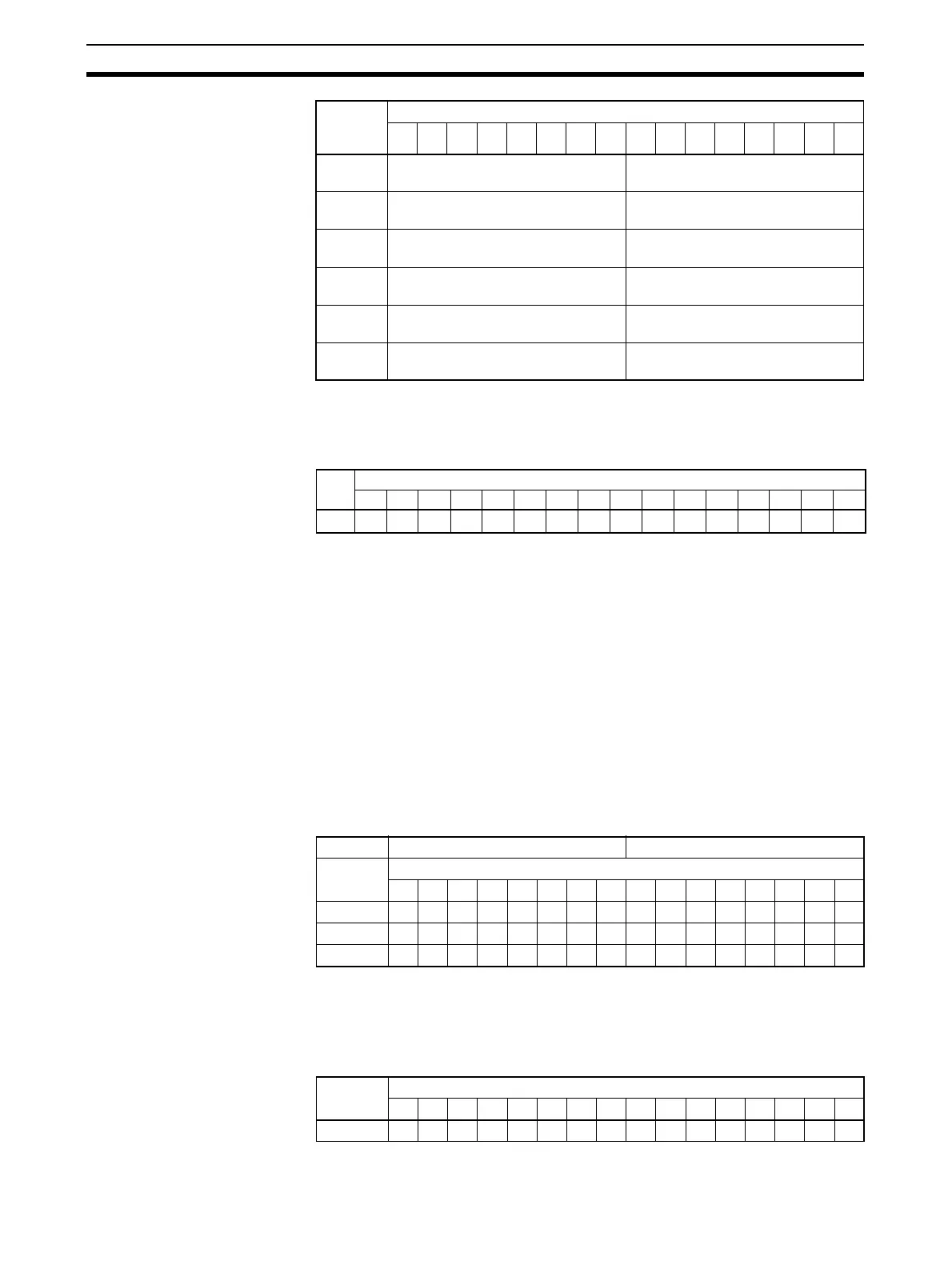
Note Word +0 is assumed to be the first address set under Bit Status on the Master
I/O Allocation Tab Page in the software setting by the CX-Integrator.
Flag Data Arrangement (Word +0)
Participation and Communications Error Flag Allocation when Expansion
Units Are Used
Allocations for the combination of a Basic Unit and Expansion Unit are the
same as for a Word Slave Unit of the same size. When inputs and outputs
are both included by adding an Expansion Unit, the Unit is treated as an
Input Unit. Therefore the Participation Flags and Communications Error
Flags corresponding to node address bits in the Input Area are used.
The following examples show flag allocations when an Expansion Unit is
connected to a Word Slave Unit at node address m (m = 0, 1, 2, etc.).
Example 1: Basic Unit (16 Inputs) + Expansion Unit (16 Inputs)
Flags for input node m are allocated.
For a Basic Unit (16 inputs) and an Expansion Unit (16 inputs) at node
address 0, the flags for IN0 are used.
Example 2: Basic Unit (16 Inputs) + Expansion Unit (16 Outputs)
Flags for input node m are allocated.
For a Basic Unit (16 inputs) and an Expansion Unit (16 outputs) at node
address 0, the flags for IN0 are used.
+26 Bit Output Slave Unit Communica-
tions Error Flags (104 to 111)
Bit Output Slave Unit Participation
Flags (104 to 111)
+27 Bit Input Slave Unit Communica-
tions Error Flags (104 to 111)
Bit Input Slave Unit Participation
Flags (104 to 111)
+28 Bit Output Slave Unit Communica-
tions Error Flags (112 to 119)
Bit Output Slave Unit Participation
Flags (112 to 119)
+29 Bit Input Slave Unit Communica-
tions Error Flags (112 to 119)
Bit Input Slave Unit Participation
Flags (112 to 119)
+30 Bit Output Slave Unit Communica-
tions Error Flags (120 to 127)
Bit Output Slave Unit Participation
Flags (120 to 127)
+31 Bit Input Slave Unit Communica-
tions Error Flags (120 to 127)
Bit Input Slave Unit Participation
Flags (120 to 127)
Word
(See
note.)
Bit
15 14 13 12 11 10 09 08 07 06 05 04 03 02 01 00
Bits
15 14 13 12 11 10 09 08 07 06 05 04 03 02 01 00
Node
address
OUT7 OUT6 OUT5 OUT4 OUT3 OUT2 OUT1 OUT0 OUT7 OUT6 OUT5 OUT4 OUT3 OUT2 OUT1 OUT0
Communications Error Flags Participation Flags
Word Bits
15 14 13 12 11 10 09 08 07 06 05 04 03 02 01 00
+0
+1
IN0 IN0
+2
Word
address
Bits
15 14 13 12 11 10 09 08 07 06 05 04 03 02 01 00
+0