67
Connecting Cables Section 4-2
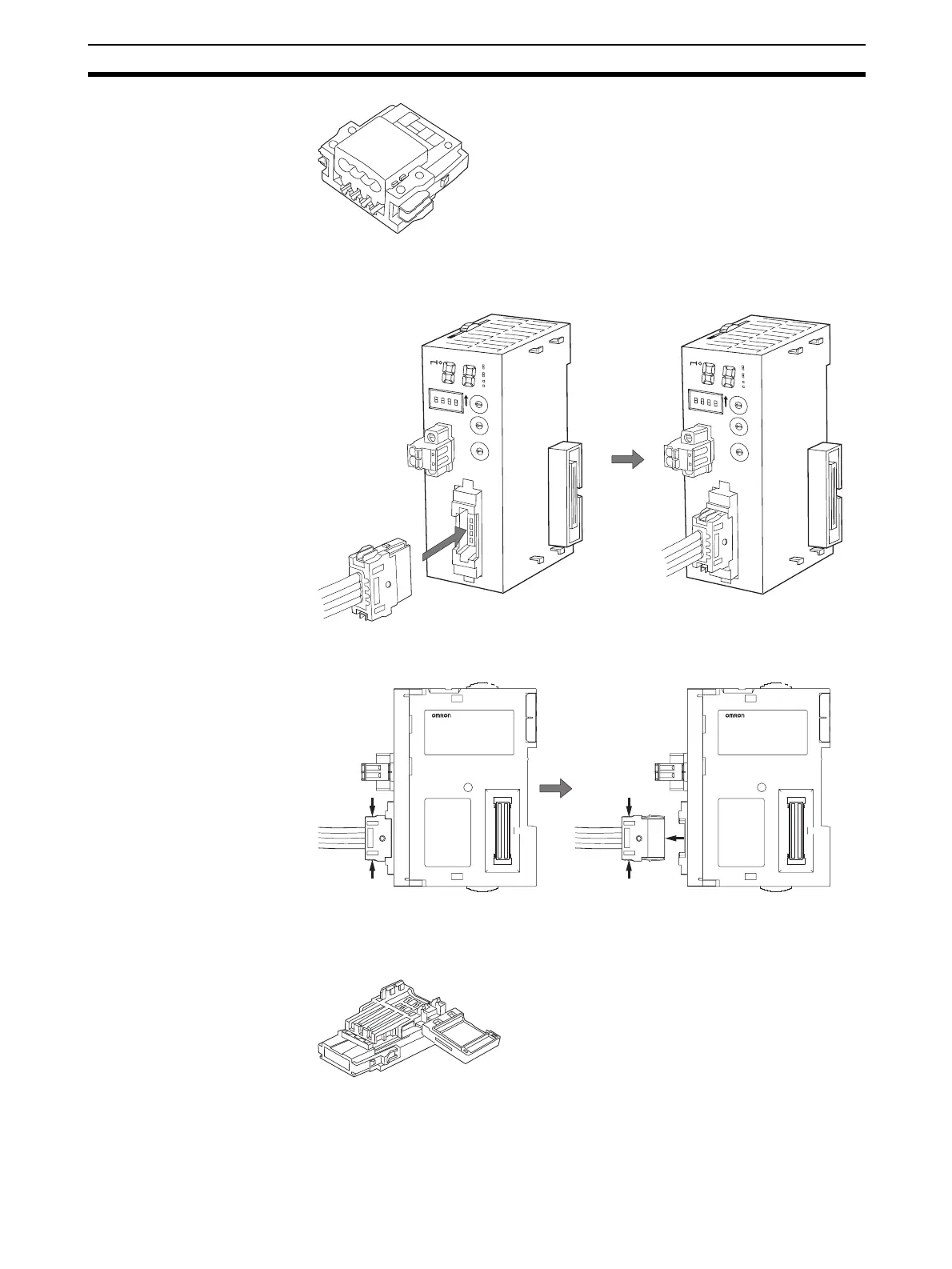
Be sure the face of the Connector on which line colors are indicated (red,
white, blue, and black) is facing to the left and press in the Connector until it
clicks into place.
Note To remove an inserted Connector, hold the latches on both sides,
and pull out the Connector.
Flat Cable II A DCN4-BR5 Flat Connector Plug is connected to the communications con-
nector on the Master Unit. Refer to 4-3 Preparing and Mounting Flat Connec-
tors.
Orient the Connector so that the white line on the cable is facing to the left and
press in the Connector until it clicks into place.
C
R
M
2
1
+
1
0
0
M
S
N
S
SD
RD
M
ACH
No.
MODE
X
1
0
1
O
N
X
10
0
BS+
BS-
D
C
24V
IN
P
U
T
BS+
BD H
DB L
BS
-
SW
1234
1
2
3
4
0
1
2
3
4
5
6
7
8
9
0
1
2
3
4
5
6
7
8
9
0
1
2
3
4
5
6
7
8
9
NETWORKPS
C
R
M
2
1
+
1
0
0
M
S
N
S
SD
RD
M
ACH
No.
M
ODE
X
1
0
1
O
N
X
1
0
0
BS+
BS-
D
C
24V
IN
P
U
T
BS+
BD H
DB L
BS
-
SW
1234
1
2
3
4
0
1
2
3
4
5
6
7
8
9
0
1
2
3
4
5
6
7
8
9
0
1
2
3
4
5
6
7
8
9
NETWORKPS