30
Wiring Terminals Section 2-2
• The voltage output (for driving SSR) is not electrically isolated from the
internal circuits. Therefore, when using a grounding thermocouple, do not
connect any of the control output terminals to the ground. If a control out-
put terminal is connected to the ground, errors will occur in the measured
temperature as a result of leakage current. With E5AN/EN, however, con-
trol output 2 (voltage output for driving SSR) is functionally isolated from
the internal circuits.
• Control output 2 of the E5CN is a voltage output (for driving SSR) only,
and outputs across terminals 11(+) and 12(
−), or 14(+) and 15(−).
• Control output 1 (voltage output for driving SSR) and control output 2
(voltage output for driving SSR) are not isolated.
• Long-life relay outputs use semiconductors for switching when closing
and opening the circuit, thereby reducing chattering and arcing and
improving durability. However, if high levels of noise or surge are imposed
between the output terminals, short-circuit faults may occasionally occur.
If the output becomes permanently shorted, there is the danger of fire due
to overheating of the heater. Design safety into the system, including
measures to prevent excessive temperature rise and spreading of fire.
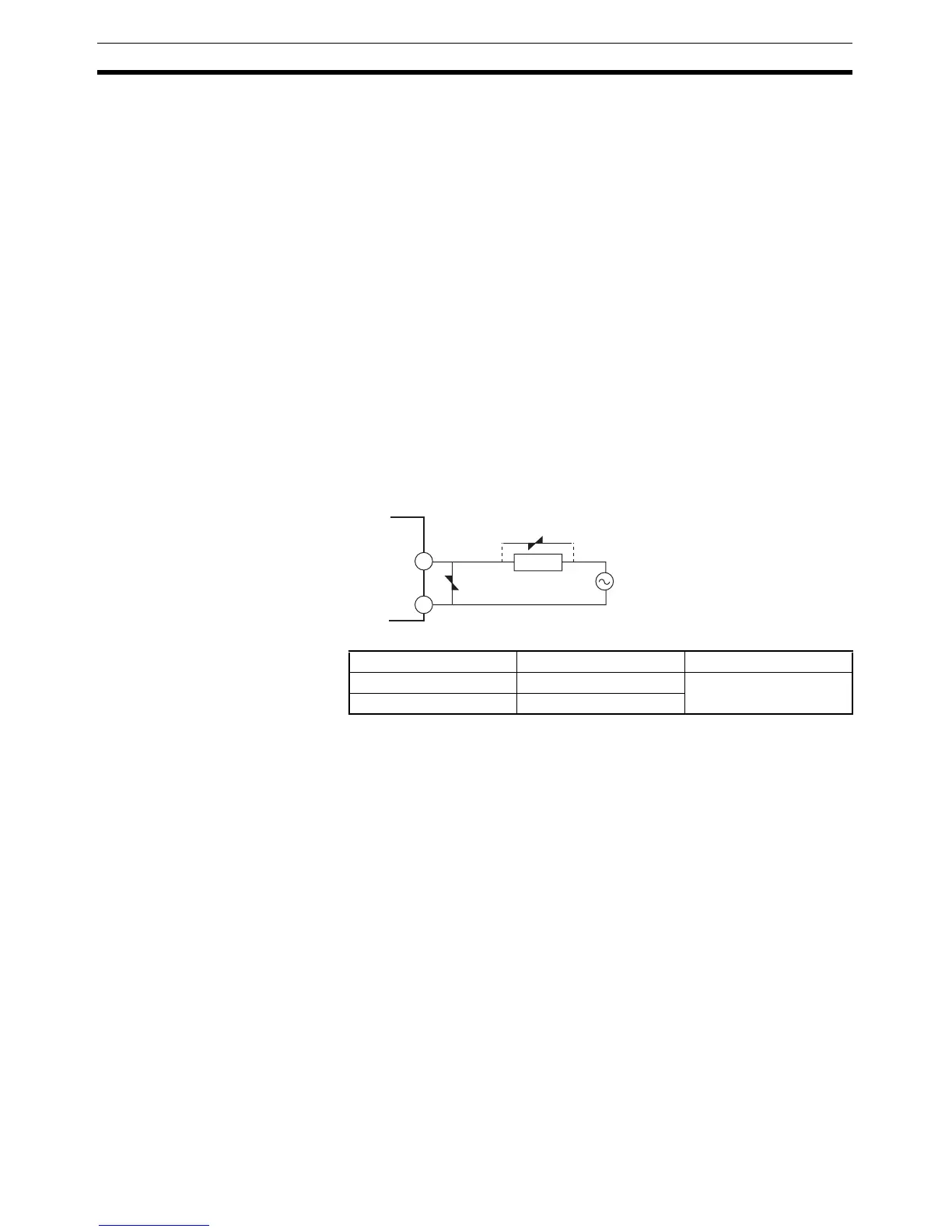
• Take countermeasures such as installing a surge absorber. As an addi-
tional safety measure, provide error detection in the control loop. (Use the
Loop Burnout Alarm (LBA) and HS alarm that are provided for the E5@N.)
Select a surge absorber that satisfies the following conditions.
Auxiliary Outputs 1, 2, and
3
• On the E5CN-@ 2@@@, auxiliary output 1 (SUB1) is output across termi-
nals 7 and 8, and auxiliary output 2 (SUB2) is output across terminals 6
and 8.
• On the E5CN-@1@@@U, auxiliary output 1 (SUB1) is output across termi-
nals 7 and 8.
• On the E5CN-@2@@@U, auxiliary output 1 (SUB1) is output across termi-
nals 7 and 8, and auxiliary output 2 (SUB2) is output across terminals 7
and 9.
• On the E5AN/EN-@3@@@, auxiliary output 1 (SUB1) is output across ter-
minals 9 and 10, auxiliary output 2 (SUB2) is output across terminals 7
and 8, and auxiliary output 3 (SUB3) is output across terminals 5 and 6.
• When the Input Error Output parameter is set to ON, the output assigned
to the alarm 1 function turns ON when an input error occurs.
• When the HB alarm, HS alarm, or heater overcurrent alarm is used with
the E5CN-@M@ with an E53-CNH/HHN2 Option Board, alarms are output
to the output assigned to the alarm 1 function.
• When the HB alarm, HS alarm, or heater overcurrent alarm is used with
the E5CN-@M@ with an E53-CNH/HHN2 Option Board, alarms are output
to the output assigned to the alarm 1 function.
Voltage used Varistor voltage Surge resistance
100 to 120 VAC 240 to 270 V 1,000 A min.
200 to 240 VAC 440 to 470 V
1
2
Long-life
relay output
Varistor
Varistor
Inductive
load