31
Wiring Terminals Section 2-2
• On the E5CN and E5CN-U, when heating/cooling control is used, auxil-
iary output 2 becomes control output (cooling).
• On the E5AN and E5EN, when heating/cooling control is used, auxiliary
output 3 becomes control output (cooling).
• For models that have a heater burnout alarm, an OR of the alarm 1 func-
tion and the HB alarm, HS alarm, or heater overcurrent alarm is sent to
the output assigned to the alarm 1 function (auxiliary output 1). If the
alarm 1 function is to be used for HB alarm only, set the alarm 1 type to 0
(i.e., do not use alarm 1 function).
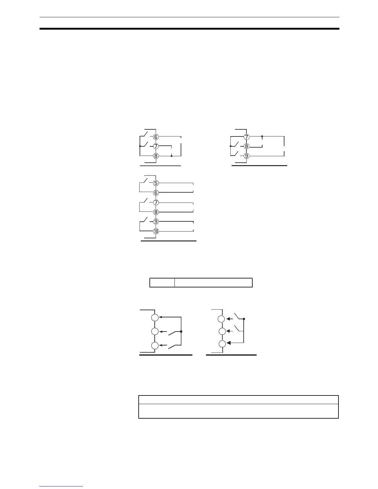
• The following diagrams show the internal equalizing circuits for auxiliary
outputs 1, 2, and 3.
ALM1, 2, 3 can be output to auxiliary output 1, 2, 3, or changed with the
advanced function setting level.
• The relay specifications are as follows:
Event Inputs • The E5@N-@@@B supports event inputs. When event inputs 1/2 are to be
used, connect to terminals 11 to 13.
• Use event inputs under the following conditions:
• The outflow current is approximately 7 mA.
E5@N
SPST-NO, 250 VAC, 3 A
E5CN E5CN-U
SUB2
SUB1
SUB3
SUB2
SUB1
E5AN/EN
SUB2
SUB1
Contact input ON: 1 kΩ max., OFF: 100 kΩ min.
No-contact input ON: Residual voltage 1.5 V max.; OFF: Leakage current
0.1 mA max.
EV1
EV2
12
11
13
EV1
EV2
11
12
13
E53-AKB in the
E5AN/EN-@M@-500-N
(for E5AN/EN)
E53-CN@B@N2 in the
E5CN-@M@-500