32
Wiring Terminals Section 2-2
Polarities during no-contact input are as follows:
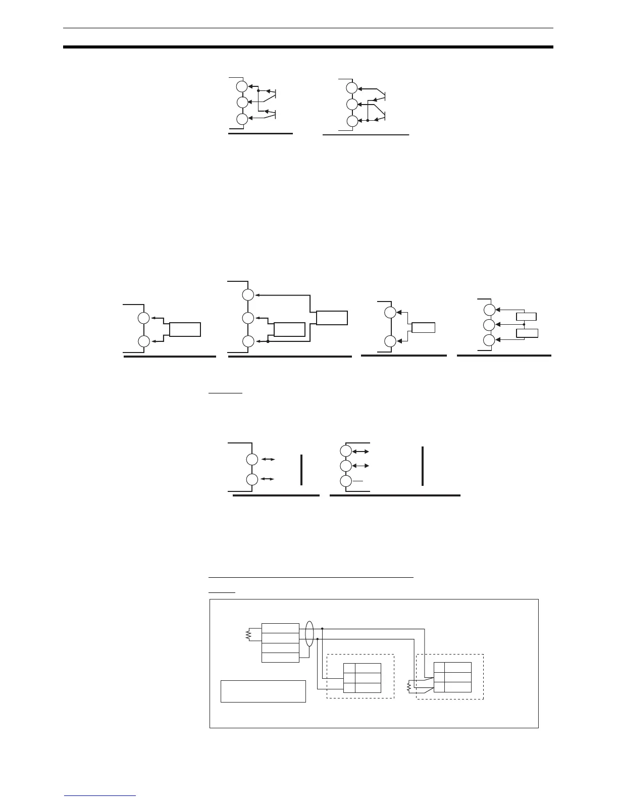
CT Inputs • When the HB alarm, HS alarm, or heater overcurrent alarm is to be used
with the E5CN-@M@-500 with an E53-CN@ H/HH@N2 Option Unit, con-
nect a current transformer (CT) across terminals 14 and 15 or terminals
13 and 15 (no polarity).
• When the HB alarm, HS alarm, or heater overcurrent alarm is to be used
with the E5AN/EN-@@H@-500-N or E5AN/EN-@@HH@-500-N, connect a
current transformer (CT) across terminals 14 and 15 or terminals 15 and
16 (no polarity).
Communications RS-485
• When communications are to be used with the E53-CN@03N2 (for E5CN)
or E53-EN03 (for E5AN/EN), connect communications cable across ter-
minals 11 and 12.
Specify both ends of the transmission path including the host computer as
end nodes (that is, connect terminators to both ends).
The minimum terminal resistance is 54
Ω.
Communications Unit Connection Diagram
E5CN
EV1
EV2
+
−
+
EV1
EV2
+
−
+
11
12
13
11
12
13
E53-CN@B@N2 in
the E5CN-@M@-500
(for E5CN)
E53-AKB in the
E5AN/EN-@M@-500-N
(for E5AN/EN)
E53-CN@@H@N2
(for E5CN)
15
14
CT
E53-CN@HH@N2
15
14
13
CT1
CT2
CT
E5AN/EN-@@H@-500-N E5AN/EN-@@HH@-500-N
CT2
CT1
14
15
14
15
16
E53-CN@03N2
(for E5CN)
11
12
RS-485
A(−)
B(+)
E53-EN03
(for E5AN/EN)
RS-485
Do not use.
13
A(−)
12
B(+)
11
No.
12
11
A (−)
B (+)
A (−)
B (+)
RS-485
−
+
FG
No.
12
11
RS-485
E5CN (No. 1)
E5CN (No. 31)
RS-485
Host computer
Shield
Terminator (120 Ω, 1/2 W)
Abbreviation Abbreviation
A < B: [1] Mark
A > B: [0] Space