7 Digital I/O Slave Unit
7 - 40
GX-series EtherCAT Slave Unit User’s Manual
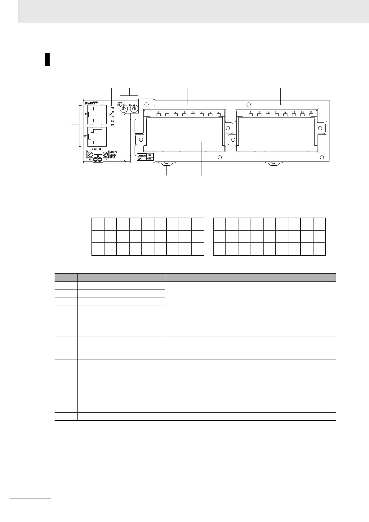
Terminal arrangement diagram
Names and functions
No. Name Function
(1) Communications connectors
Refer to "6-3 Specifications of Common Areas" in Page 6 - 4.
(2) Unit power supply connector
(3) Status indicators
(4) Node Address setting Switches
(5) Input indicators (0 to 7)
Indicates the state of an input contact (ON/OFF).
Not lit: Contact OFF (input OFF state)
Lit in yellow: Contact ON (input ON state)
(6) Output indicators (0 to 7)
Indicates the state of an output contact (ON/OFF).
Not lit: Contact OFF (output OFF state)
Lit in yellow: Contact ON (output ON state)
(7) Terminal block
Connects external devices and the I/O power supply.
<Left side>
V1, G1: Input side I/O power supply terminals
0 to 7: Input terminals
<Right side>
V2, G2: Output side I/O power supply terminals
0 to 7: Output terminals
(8) DIN track mounting hook Fixes a Slave Unit to a DIN track.
(5)
(1)
(7)
(2)
(3)
(4)
(6)
(8)
10 to 18
1 to 9
19 to 27
NC
0123
4567
V1 V1 V1 V1 V1 V1 V1 V1
G1 G1 G1 G1 G1 G1 G1 G1
V1
G1
NC
0123
4567
V2 V2 V2 V2 V2 V2 V2 V2
G2 G2 G2 G2 G2 G2 G2 G2
V2
G2

 Loading...