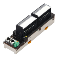
7 Digital I/O Slave Unit
7 - 52
GX-series EtherCAT Slave Unit User’s Manual
Precautions for Correct Use
• The I/O power supply connectors are equipped with two sets of V and G terminals. One set of
terminals is used for the I/O power supply for the unit, and the other set is used for the I/O
power supply to the next unit. Use a maximum current of 4 A per terminal.
• When using an inductive load, such as a solenoid valve, either use a built-in diode for
absorbing the counterelectromotive force or install an external diode. (Refer to "A-4 Wiring
External Output Signal Lines" in Page A - 78.)
Wire colors have been changed according to revisions in the JIS standards for photoelectric and
proximity sensors. The colors in parentheses are the wire colors prior to the revisions.

 Loading...