9 Encoder Input Slave Unit
9 - 22
GX-series EtherCAT Slave Unit User’s Manual
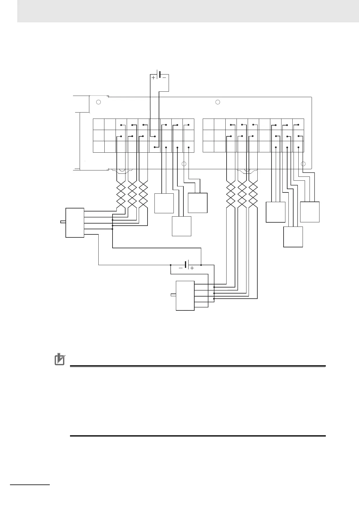
Precautions for Correct Use
• Use shielded cable and ground the shield to 100 Ω or less when wiring pulse input A/B/Z with
external control inputs.
• Wiring of pulse input A/B/Z shall be as short as possible and separated from wiring with many
noises such as power lines.
• Use stabilizing power supply separate from other inputs/outputs for Encoder Input Slave Units
as much as possible.
• Do not wire anything to RSV terminals.
• V1, G1, V2, and V2 terminals shall be wired as shown in the above wiring diagram.
RSV
RSV V1 V1 V1
RSV LA1 LB1
RST1
V1 V1 A24 B24 Z24 V2 V2 V2
G1 G1 A5 B5 Z5 G2 G2 G2
V2
G2
RSV
RSV V1 V1 V1
RSV LA2 LB2
RST2
V1 V1 A24 B24 Z24 V2 V2 V2
G1 G1 A5 B5 Z5 G2 G2 G2
V2
G2
Phase
A
Black
Blue
Latch
Black
Blue
Reset
Black
Blue
Latch
Phase
B
Phase
Z
Encoder power supply
(24 VDC or 5 VDC)
Blue
:
0V
Brown
:
Vcc
Black
:
Phase A
White
:
Phase B
Orange
:
Phase Z
Encoder
(NPN open collector
output type)
Sensor power supply
(24 VDC)
NPN output
3-wire sensor
Output
2-wire sensor
Encoder
(NPN open collector
output type)
Black
Brown
Blue
Latch
Black
Brown
Blue
Latch
Black
Brown
Blue
Reset

 Loading...