10 IO-Link Master Unit
10 - 12
GX-series EtherCAT Slave Unit User’s Manual
*1 I/O power supply to devices:
This is the voltage and current value supplied to devices when the communications modes of the ports on the
IO-Link Master Unit are IO-Link Mode or SIO (DI) Mode. Check the power consumption of the connected
device and supply the power from the I/O power supply to the IO-Link Master Unit.
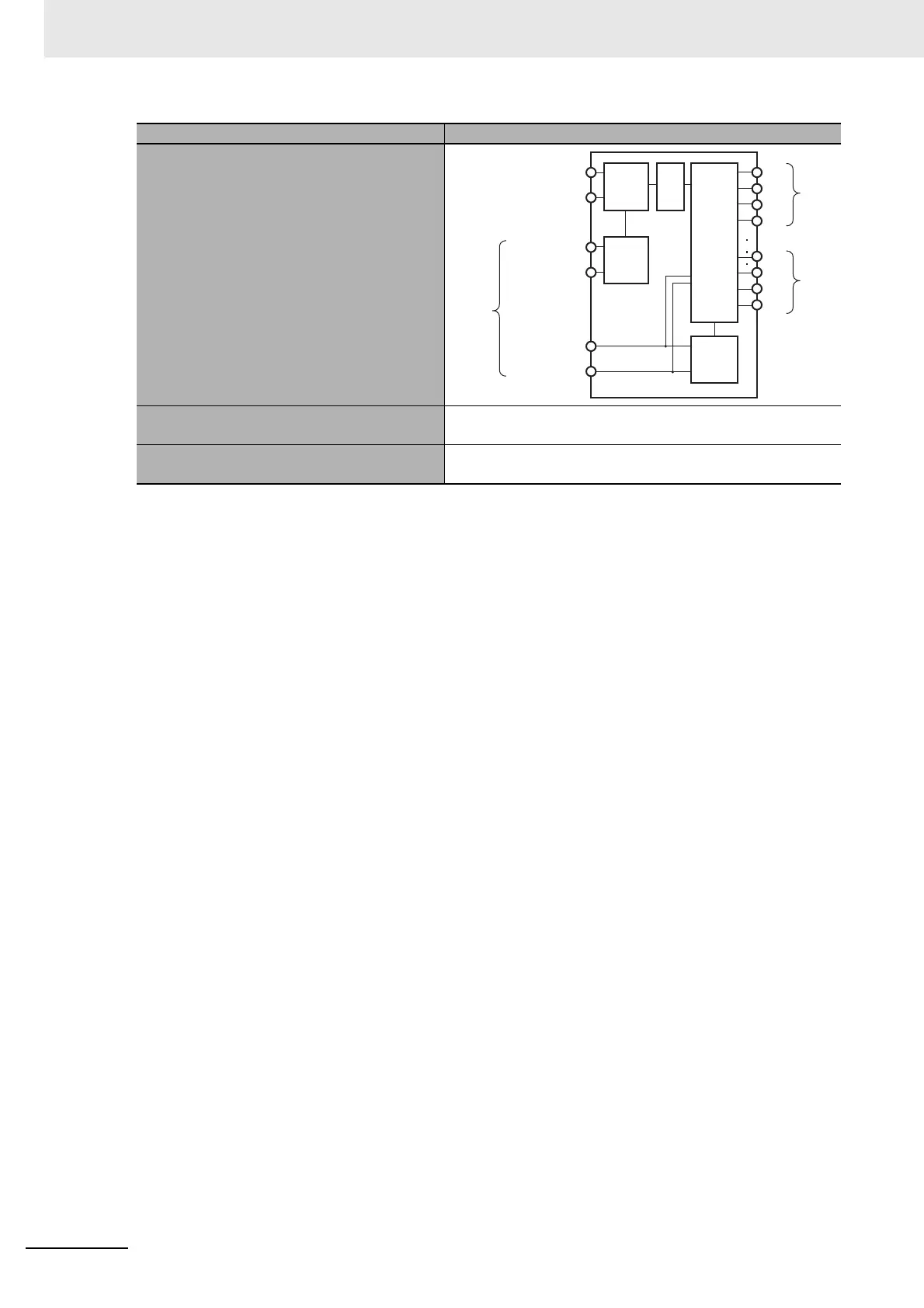
Circuit layout
Installation orientation and restrictions
Installation orientation: 6 possible orientations
Restrictions: No restrictions
Protective functions
•
Short-circuit protection for L+ terminal
• Short-circuit protection for C/Q terminal
Item Specification
IN communications
connector
OUT communications
connector
Power
supply
connector
Unit power supply
24 V
Unit power supply
0 V
I/O power
supply 24 V
I/O power
supply 0 V
Internal
circuits
I/O
connector
1
I/O
connector
8
L+
C/Q
DI
L-
L+
C/Q
DI
L-
Non-isolated
power supply
circuits
Non-
isolated
power
supply
circuits
IO-Link
circuits
Isolation
circuit

 Loading...