3-93
3 Functions of NB-Designer
NB-series Programmable Terminals NB-Designer Operation Manual(V106)
3-6 Parts
3
3-6-5 Word Lamp
Process of adding one Word Lamp component
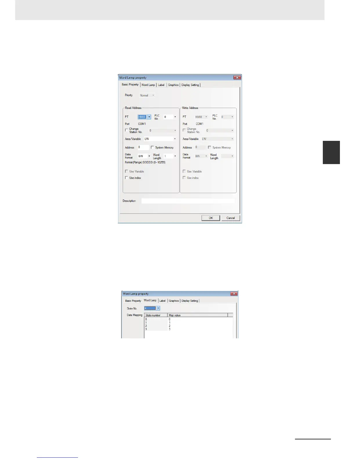
1
Drag the Word Lamp component icon after it is pressed will make the [Basic Properties] of
Word Lamp component pop up.
Read Address: Refers to the PLC address controlling the displayed information (such as the
state, graphics, label and so on) of the Word Lamp component.
Address: The first address of word address corresponding to the Word Lamp component.
Word Length: Displays the data length of the Read Address, and 1 and 2 are available (i.e.
word or double-word).
2
Switch to the [Word Lamp] tab and set the state for the Word Lamp component. You can set the
state from 1 to 256 in the dropdown box corresponding to “State No.”.
Map Value: Refers to the value corresponding to each state. When the value of read address
is equal to the map value, the state number corresponding to this value will be displayed.
3
Switch to the [Label] tab and add the different displayed texts corresponding to the different
states.
4
Switch to the [Graphics] tab and select Vector Graphics or bitmap to display the graphics
corresponding to the state of the Word Lamp component.
5
Press the [OK] button to complete the setup of the Word Lamp component.

 Loading...


