3-8 Installing the Controller Link Interface Unit
3-57
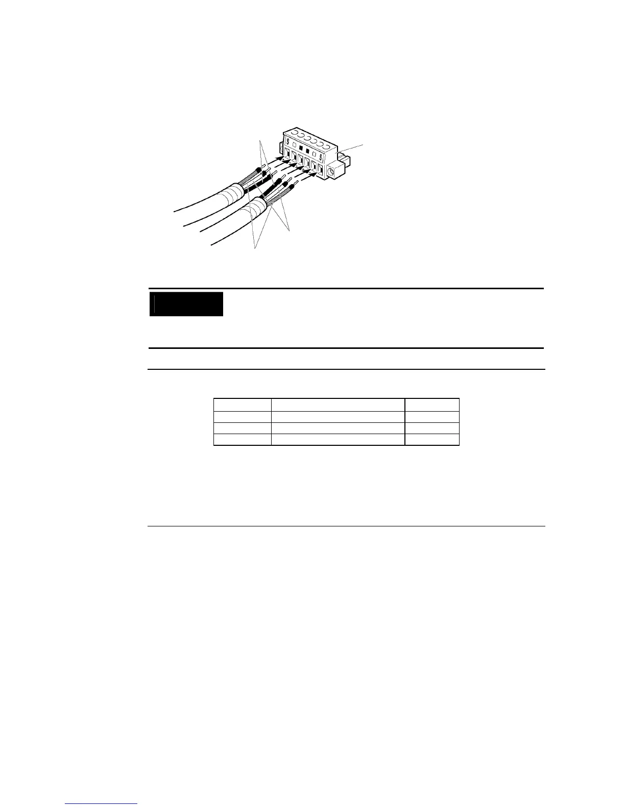
6. Carefully insert the signal and shield lines into the respective holes of the connector
(identified with the markings). Ensure that the connector is oriented correctly. The follow-
ing example is for connection to a Board in the middle of the network.
Cable connecto
Shield lines
BD H
BD L
Precautions
for Safe Use
• Loosen the screws in the connector enough to allow the terminal to pass be-
fore inserting the signal line. If the screw is not loosened, the signal line will
go completely into the connector and you will not be able to secure the line.
• Attach crimp terminals to the wires. Never connect bare power supply wires
directly to the connector.
Reference •
Marks are provided on the connector for the signal lines. Connect the signal lines ac-
cording to the marks.
• Marks indicate signals as listed above.
• The lines can be connected to either the right or left half of the connector at the node
on either end of the network.
• If grounding by node, the connection method for the shield is different.
Refer to Wiring Communications Cable and Connecting the Shield Line to the Connec-
tor under 3-8-4 Wiring, for details on connecting the shield to the connector.
7. Firmly secure each signal line with the signal line screws in the connector. An ordinary
flat-blade screwdriver with a tip that tapers at the end is not suitable because it cannot
be inserted far enough. Use a small flat-blade screwdriver with a uniform width. The ap-
plicable tightening torque is 0.2 N⋅m.
Marking Signal name Line color
BD H (communications data high) Black
BD L (communication data low) White
S SHLD (shield)
−