5-1 Connecting to Host Via Ethernet
5-8
Unit number 04
U
nit number 02
Network 2
Network 3
Local network table
Local network
address
Unit number
2 02
3 04
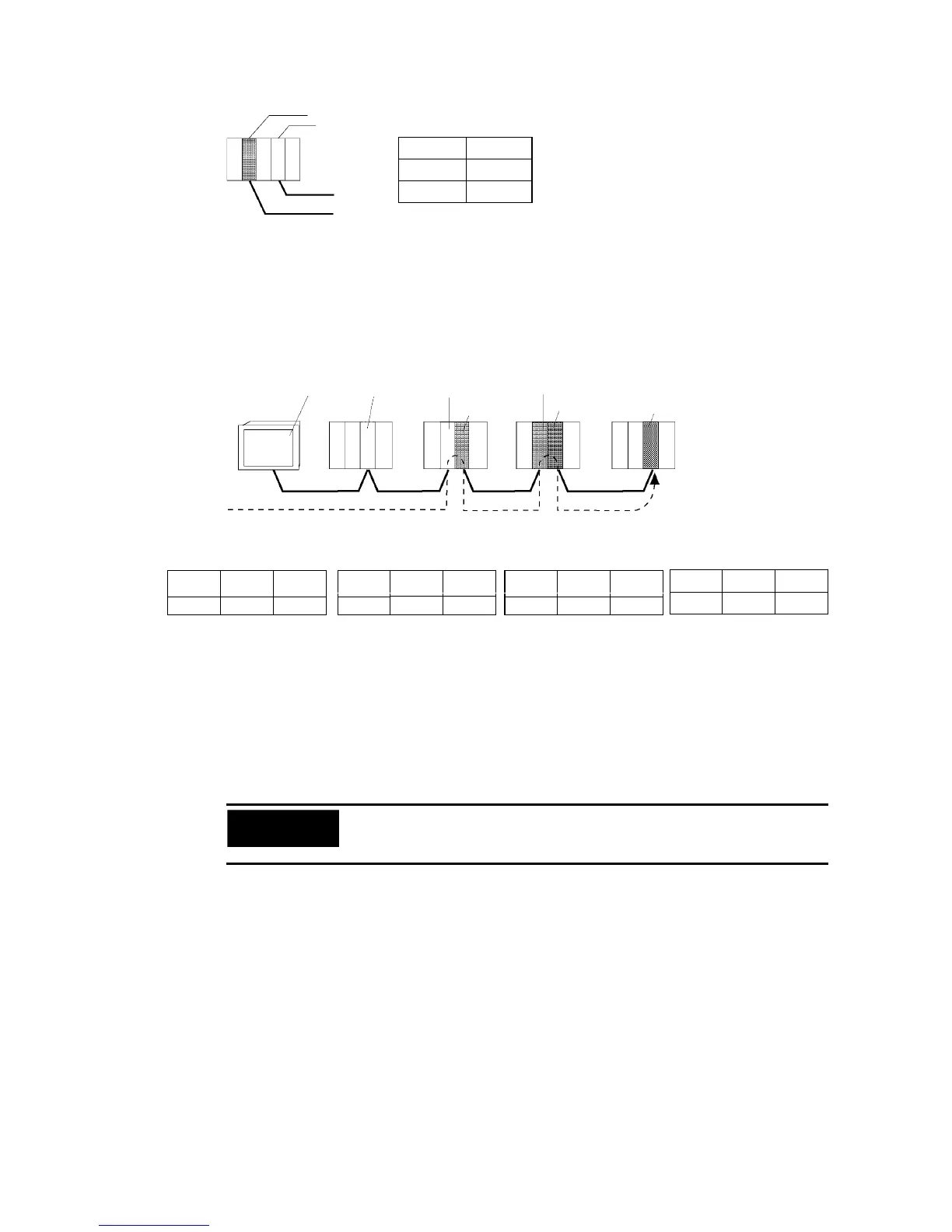
Remote Network Table
The remote network table provides the node and network address corresponding to the ini-
tial relay point (first point the data must pass) en route to a target network (end network) not
directly connected to the local PLC. The table specifies the route from the relay point to the
end network.
PT at local
node
Node 1 Node 2
Node 3
Relay PLC
(a)
Node 2
Relay PLC
(b)
Node 1
Desti-
nation
Node 2
Network 1 Network 2 Network 3
Node 1
Relay Network Table for Local PT
Destination
network
address
3
1
3
Relay
network
address
Gateway
node
address
Meaning: To go to network 3,
first go to node 3 of network 1.
Relay Network Table for PLC (a)
3
2 2
Destination
network
address
Gateway
node
address
Relay
network
address
Meaning: To go to network 3,
first go to node 2 of network 2.
Relay Network Table for PLC (b)
1 2 1
Meaning: To go to network 1,
first go to node 1 of network 2.
Relay Network Table for Destination
Destination
network
address
Relay
network
address
Gateway
node
address
1 3 1
Meaning: To go to network 1,
first go to node 1 of network 3.
Destination
network
address
Gateway
node
address
Relay
network
address
Routing tables are created using the CX-Programmer and then transferred to the host. Refer
to the CX-Programmer User Manual for actual procedures.
The methods for setting each Unit are described next.
• CS-series PLCs
Precautions
for Safe Use
• Always turn OFF the power to the PLC before setting the rotary switches.
• Create I/O tables for the CPU Unit when setting the unit number for the first
time or changing settings.
CS1G/CS1H and CS1G/CS1H-H Ethernet Units:
CS1W-ETN01
CS1W-ETN11
CS1W-ETN21