154
Overview of Direct Connection Operations
Section 5-1
Controlling the NT20S Status by Using Allocated Bits and Words ..... PT Status Control Area (PC to PT)
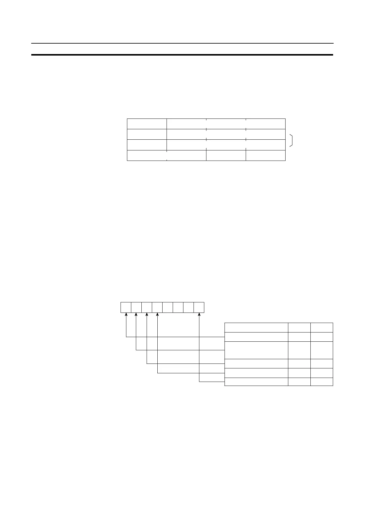
The PT status control area (PC to PT) is provided to control the NT20S status from
the PC. When data is written to this area in the PC, the NT20S will read the data
and operates according to the data. The PT status control area is configured as
four consecutive words as shown below.
0
Copy type
0 0
The first word (word n) of the PT status control area must be set with the support
tool.
S Screen switch settings (refer to page 157)
Specify the screen # to switch the screen displayed on the NT20S.
S Copy memory table settings (refer to page 174)
Specify the memory table # to copy the contents of a memory table internally in
the NT20S.
Set the copy type to match the type of memory table to be copied:
0: Character-string memory table
1: Numeral memory table
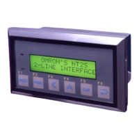
S PT status control bits (refer to page 191)
These bits are switched ON and OFF to control the NT20S buzzer and backlight.
000
15 14 13 12 11 10 9 8 Bit
n+3 CH
Note 1:When “ON” is set for screen display, the
backlight is on; when “OFF” is set for
screen display, the backlight is off.
Note 2:Priority registration is only valid when NT
link (1:N) is set.
OFF
Item Controlled
Screen display (Note 1) ON OFF
Processing priority
registration (Note 2)
ON OFF
Continuous buzzer
Intermittent buzzer
ON OFF
ON
1(ON) 0(OFF)
Backlight mode
Flash
ON
Word1514131211109876543210Bit
Screen # (4-digit BCD)
Screen switch
setting
Copy memory
table setting
Copy destination memory table # (3-digit BCD)
Copy source memory table # (3-digit BCD)
PT status control bit
PT status control
n
n+1
n+2
n+3