157
Overview of Direct Connection Operations
Section 5-1
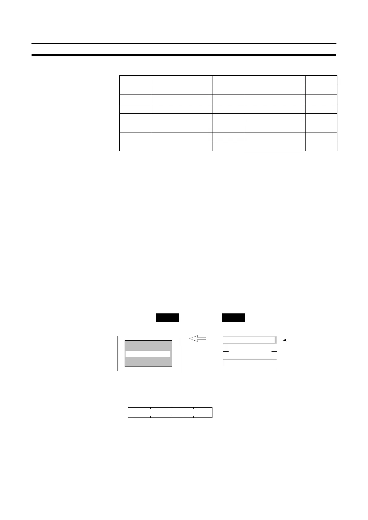
The PT status control area (PC to PT) can be allocated to the following PC areas.
Symbol C Series PCs Allocated CVM1/CV Series PCs Allocated
DM Data Memory f Data Memory f
CH Internal/Special Relay f Internal/Special Relay f
TIM Timer Timer
CNT Counter Counter
HR Holding Relay f –
AR Auxiliary Relay f Auxiliary Relay
LR Link Relay f –
f: OK : NG
Since the special auxiliary relays of the CVM1/CV series PCs are allocated to the
system, they cannot be used for purposes other than the system use.
Correct Use: Make sure there is no duplication in the PT status control area allocations and PT
status notify area allocations.
Reference: When NT link (1:N) is set, the PT status control area must be set for each con-
nected PT.
5-1-4 Switching the Screen Display
The following describes the procedure used to switch the NT20S screen display by
controlling from the PC.
Reference: The display screen can be switched also by pressing a touch switch during the op-
eration after registering a screen number to the touch switch. For this function,
refer to the “Standalone Function“ (page 138).
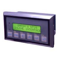
To switch the NT20S screen display by controlling from the PC, write a screen
number at the “screen switch setting” in the PT status control area.
NT20S PC
Designated screen
PT status control area
Screen switch setting
PT status control setting
Screen number
Copy memory
table setting
[Screen switch setting in the PT status control area]
1514131211 10 9 8 7 6 5 4 3 2 1 0 Bit
PT status notify bits
Word n
Screen switch setting
Screen number :0000 (screen clear, no-display)
:0001 to 0500
Screen number (4-digit BCD)