1
6
9
5
258
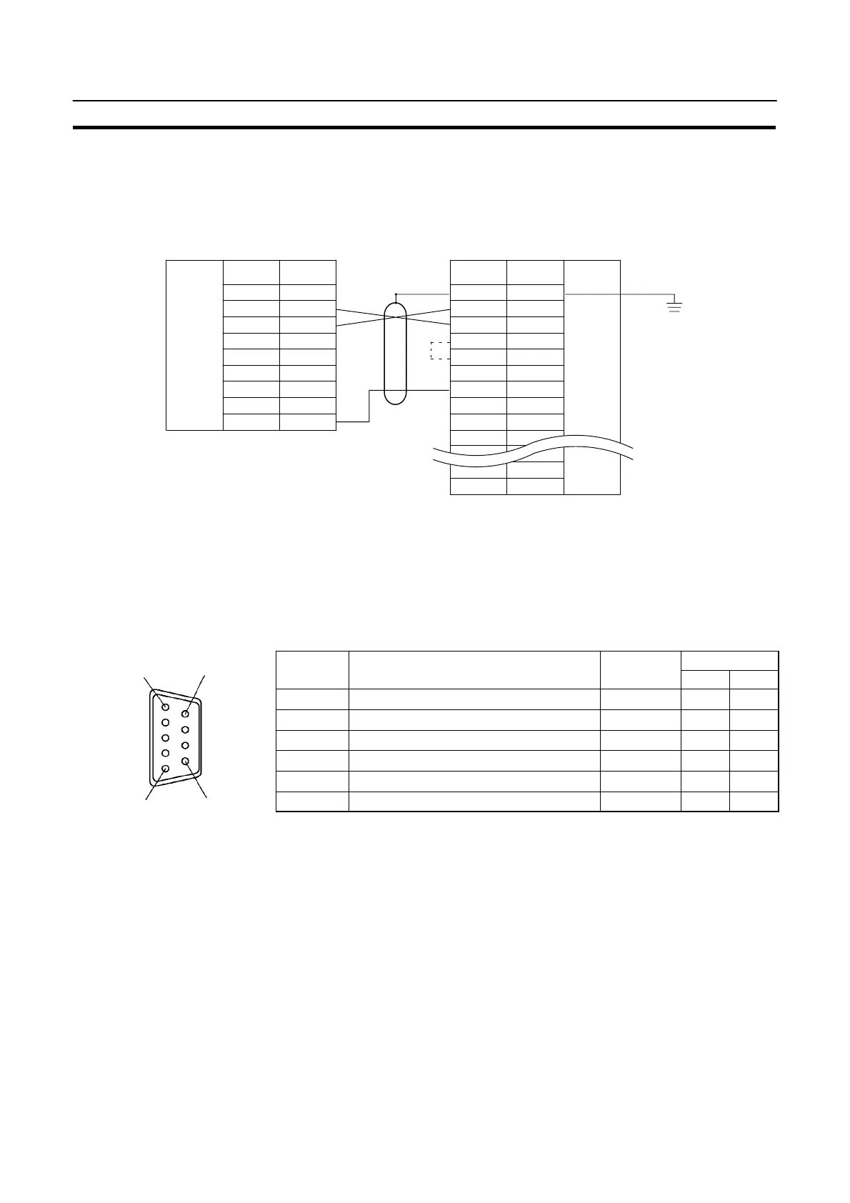
Method for Making the Cable for Connection to the Host
Appendix G
S Wiring Connections
The NT20S does not use pin 4 (RS) or pin 5 (CS). Either short the RS and CS pins of the PC connector together or
set the CTS setting selector switch at the rear face of the host link unit to “0V” (see
in the figure).
Connect the cable shielding wire to the connector cover and pin 1 at the host link unit end of the cable only.
1
2
3
4
5
6
7
8
9
Pin
number
Abbrevi-
atioon
SD
RD
RS
CS
SG
RS-232C
interface
RS-232C
interface
Pin
number
Abbrevi-
atioon
1
2
3
4
5
6
7
8
–
FG
SD
RD
RS
CS
–
SG
–
–
Shielding
wire
25-pin connector
NT20S PC (host link unit)
–
–
–
ER
–
–
–
20
Connecting an NT20S to a C-Series CPU (CjjH)
S C-Series CPU Unit (CjjH) 9-pin Connector Specifications
S Applicable CPU: C20H/C28H/C40H/C60H
S Electrical characteristics: Complies with EIA RS-232C
S Signal direction: Signal input and output is relative to the PC.
Connector
Signal Direction
Pin No.
Signal Name
Abbreviation
Input Output
1 Frame ground FG – –
2 Send data SD (TXD) f
3 Receive data RD (RXD) f
4 Request to send RS (RTS) f
5 Clear to send CS (CTS) f
7 Signal ground SG (GND) – –