Connection (1)
Connection (3)
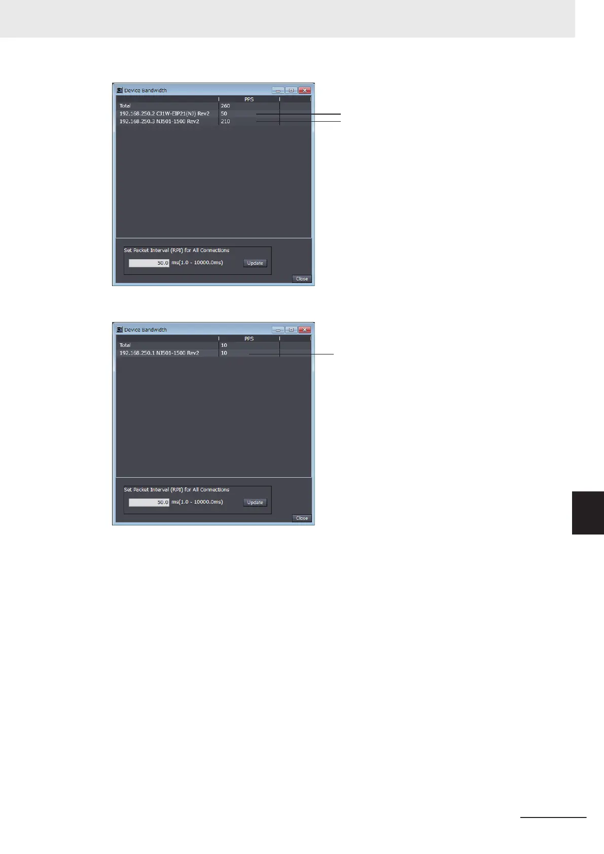
EtherNet/IP connection settings for Controller 1
EtherNet/IP connection settings for Controller 2
In this example, the PPS for Connection (1) is 50 pps, the PPS for Connection (2) is 10 pps, and
the PPS for Connection (3) is 210 pps. Therefore, bandwidth used (PPS) for each EtherNet/IP de-
vice is as given below
.
192.168.250.1: 270 pps = 50 pps (for Connection (1)) + 10 pps (for Connection (2)) + 210 pps (for
Connection (3))
192.168.250.2: 60 pps = 50 pps (for Connection (1)) + 10 pps (for Connection (2))
192.168.250.3: 210 pps = 210 pps (for Connection (3))
Adjusting Method
If the calculation result value exceeds the values in the specifications of the devices used in the
EtherNet/IP connections, re-evaluate the overall network configuration and correct it by taking
steps such as selecting a different Ethernet switch or splitting the network.
If the RPI is made longer, the PPS for the EtherNet/IP connections will decrease.
You can change the RPI values in the connection settings for all the target devices by specifying a
value in Set Packet Interval (RPI) for All Connections in this dialog box.
Appendices
A-25
NJ/NX-series CPU Unit Built-in EtherNet/IP Port User’s Manual (W506)
A-2 Use the Sysmac Studio to Set the Tag Data Links (EtherNet/IP Connections)
A
A-2-4 Making the EtherNet/IP Connection Settings with the Sysmac Stu-
dio
 Loading...


