NJ-series CPU Unit NX-series CPU Unit
10Base-T 100Base-TX 10Base-T 100Base-TX
1000Base-T
*1
• Connect the shield at both ends
or
• Connect the shield only at the Ethernet
switch side
• Connect the shield at both ends
or
• Connect the shield only at the Ethernet
switch side. A clamp core must be at-
tached to the EtherNet/IP port side of
the cable.
Connect the shield
at both ends
*1. For NX701 CPU Units only.
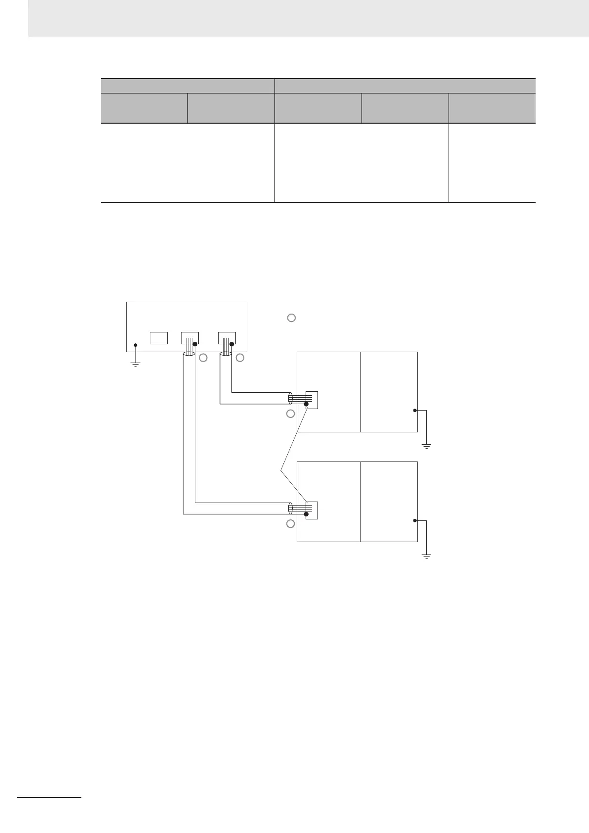
• 10Base-T or 100Base-TX
Connect the cable shields to the connector hoods as described in either (1) or (2) below
.
1. Connecting the shields at both ends of the cable
Connect the shields to the connector hoods at both ends of the cables.
STP
(
Shield)
STP
(Shield)
GR
terminal
GR
terminal
Ethernet switches
GR
terminal
Connector
Connector
Connector
ConnectorConnector
Connect shield to connector hood
Built-in
EtherNet/IP port
Built-in EtherNet/IP port
on NX-series CPU Unit
Power Supply
Unit
Built-in EtherNet/IP port
on NJ-series CPU Unit
Power Supply
Unit
2. Connecting the shields only at the Ethernet switch side
Connect the shields to the connector hoods only at the Ethernet switch side.
•
For an NX-series CPU Unit, a clamp core must be attached to the end of the cable at the
EtherNet/IP port side. For a recommended clamp core and attachment methods, refer to
Recommended Clamp Core and Attachment Method on page 2-10.
To comply with EMC standards, it is mandatory that a clamp core be attached when con-
necting the shield to the connector hood only at the Ethernet switch side.
• For an NJ-series CPU Unit, it is not necessary to attach a clamp core.
2 Installing Ethernet Networks
2-8
NJ/NX-series CPU Unit Built-in EtherNet/IP Port User’s Manual (W506)
 Loading...


