248
GRT1-CT1(-1) Counter Units Section 7-4
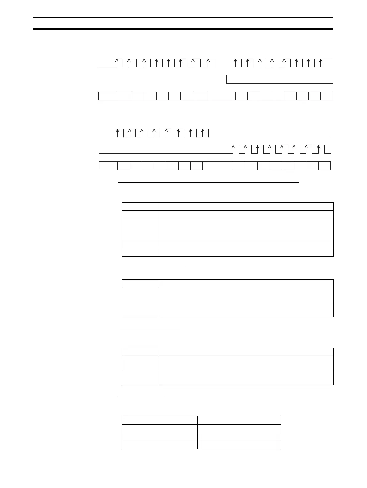
Pulse/Direction Counting
The following figure illustrates the operation of pulse/direction counting.
Up/Down Counting
The following figure illustrates the operation of up/down counting.
■ Action on Input Rising Edge and Action on Input Falling Edge
Select the action to be executed on the rising or falling edge of the digital input
(Z-phase input).
■ Action upon Bus Error
Select the action to be executed when a bus error occurs.
■ Action upon Bus Idle
Select the action to be executed when the bus goes idle (i.e., when an error
occurs in host communications, such as a DeviceNet or PROFIBUS error).
■ Default Settings
Press the Default Setting Button on the General Tab Page to set the follow-
ing default values.
2
21
1007
6
8 7
6
5
5
4
4 3
3
Input A
Input B
ON
OFF
ON
OFF
2 2 1 1 00 7 6 8 7 6 5 5 4 4 3 3
Input A
Input B
ON
OFF
ON
OFF
Action Description
No Action No action is executed.
Capture The Present Counter Value is stored in the Capture Value Register.
The captured value can be retrieved at any time using the Counter
Data Display Command Bit (bit 04 of word n+2).
Reset The counter value is reset to 0.
Preset The counter value is set to the preset value.
Action Description
Outputs are
Cleared
The output status will be cleared until the bus error is removed, but
the counter value will still be updated according to the encoder inputs.
Outputs keep
functionality
The output status will continue to be updated and the counter value
will still be updated according to the encoder inputs.
Action Description
Outputs are
Cleared
The output status will be cleared until the bus idle is removed, but the
counter value will still be updated according to the encoder inputs.
Outputs keep
functionality
The output status will continue to be updated and the counter value
will still be updated according to the encoder inputs.
Setting Default value
Counter Input Mode Phase differential ×1
Action on Input Rising Edge No Action
Action on Input Falling Edge No Action

 Loading...


