252
GRT1-CP1-L Positioning Unit Section 7-5
7-5 GRT1-CP1-L Positioning Unit
This section describes the GRT1-CP1-L Positioning Unit.
7-5-1 Specifications
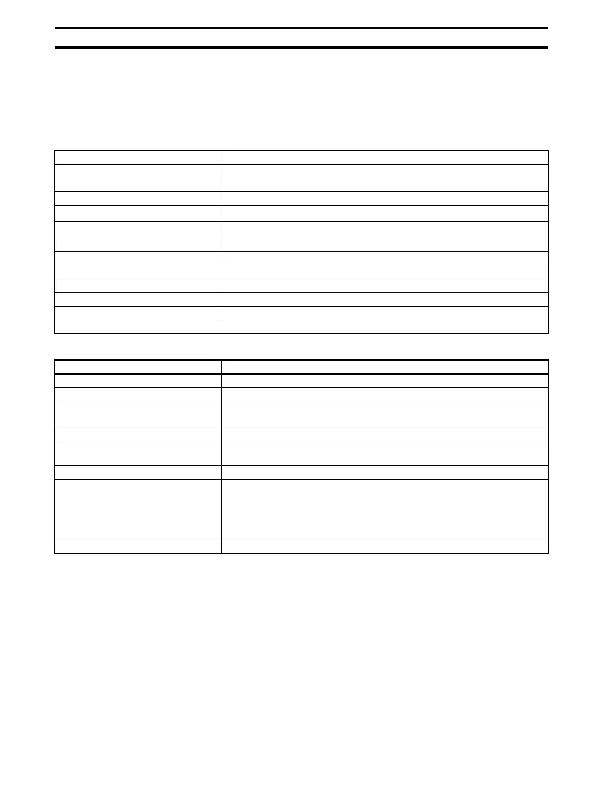
General Specifications
Performance Specifications
Note The response time is the time between the moment the A, B, Z, or IN input
turns ON or OFF and the moment the digital output is updated to the new
state. The specified response time may not be achieved during monitoring or
maintenance.
I/O Signal Specifications
The encoder A and B inputs are phase differential signals for counting. The
encoder input Z is a zero marker each revolution. The A, B and Z inputs may
be either 24 V or line driver levels according to the DIP switch setting. Refer to
Hardware Settings on page 255.
Item Specification
Unit power supply voltage 24 VDC (20.4 to 26.4 VDC)
I/O power supply voltage 24 VDC (20.4 to 26.4 VDC)
Noise immunity Conforms to IEC 61000-4-4, 2.0 kV (power lines)
Vibration resistance
10 to 60 Hz, 0.7-mm double amplitude; 60 to 150 Hz, 50 m/s
2
Shock resistance
150 m/s
2
Dielectric strength 500 VAC (between isolated circuits)
Insulation resistance 20 MΩ minimum (between isolated circuits)
Ambient operating temperature −10 to 55°C (with no icing or condensation)
Ambient operating humidity 25% to 85%
Operating environment No corrosive gases
Ambient storage temperature −25 to 65°C (with no icing or condensation)
Mounting 35-mm DIN Track mounting
Item Specifications
Input points 3 counter inputs (A, B, and Z) and 1 digital input
Output points 2 digital outputs (settable)
Signal levels for A, B, and Z counter
inputs
24 V or line driver interface
Set using a DIP switch. Refer to Hardware Settings on page 255.
Counter resolution 32-bit
Maximum pulse input frequency 100 kHz max. depending on the counter mode. Refer to I/O Signal Specifica-
tions on page 252 for details.
Overall response time 1 ms max. (See note.)
Isolation method Photocoupler isolation between communications lines and inputs/output lines.
24-V interface: No isolation between input A, input B, input Z, digital input (IN),
and digital outputs (OUT0 and OUT1).
Line-driver interface: Isolation between inputs A, B, and Z. No isolation between
digital input (IN) and digital outputs (OUT0 and OUT1).
I/O connection method Screwless Terminal block

 Loading...


