144
Analog Output Units Section 5-5
5-5-2 I/O Data and Allocation Methods
When the Analog Output Unit’s default settings are used, output data is allo-
cated. No special settings are required. Two words (four bytes) of output data
are allocated as two’s complement.
5-5-3 Functions and Setting Methods
Scaling The default setting is used to perform DA conversion, converting analog out-
put values that have been scaled to a count of 0 to 6,000 into corresponding
digital values in the output signal range. Scaling can be used to change
scaled values that correspond to the output signal range into other values
required by the user (industry unit values). Scaling also eliminates the need
for ladder programming in the Master to perform math operations. The follow-
ing two methods of scaling can be used.
Default Scaling Default scaling converts analog output values into voltage or current values.
The units used are mV or μA. When default scaling is selected, scaling is per-
formed according to the output range, as shown in the following table.
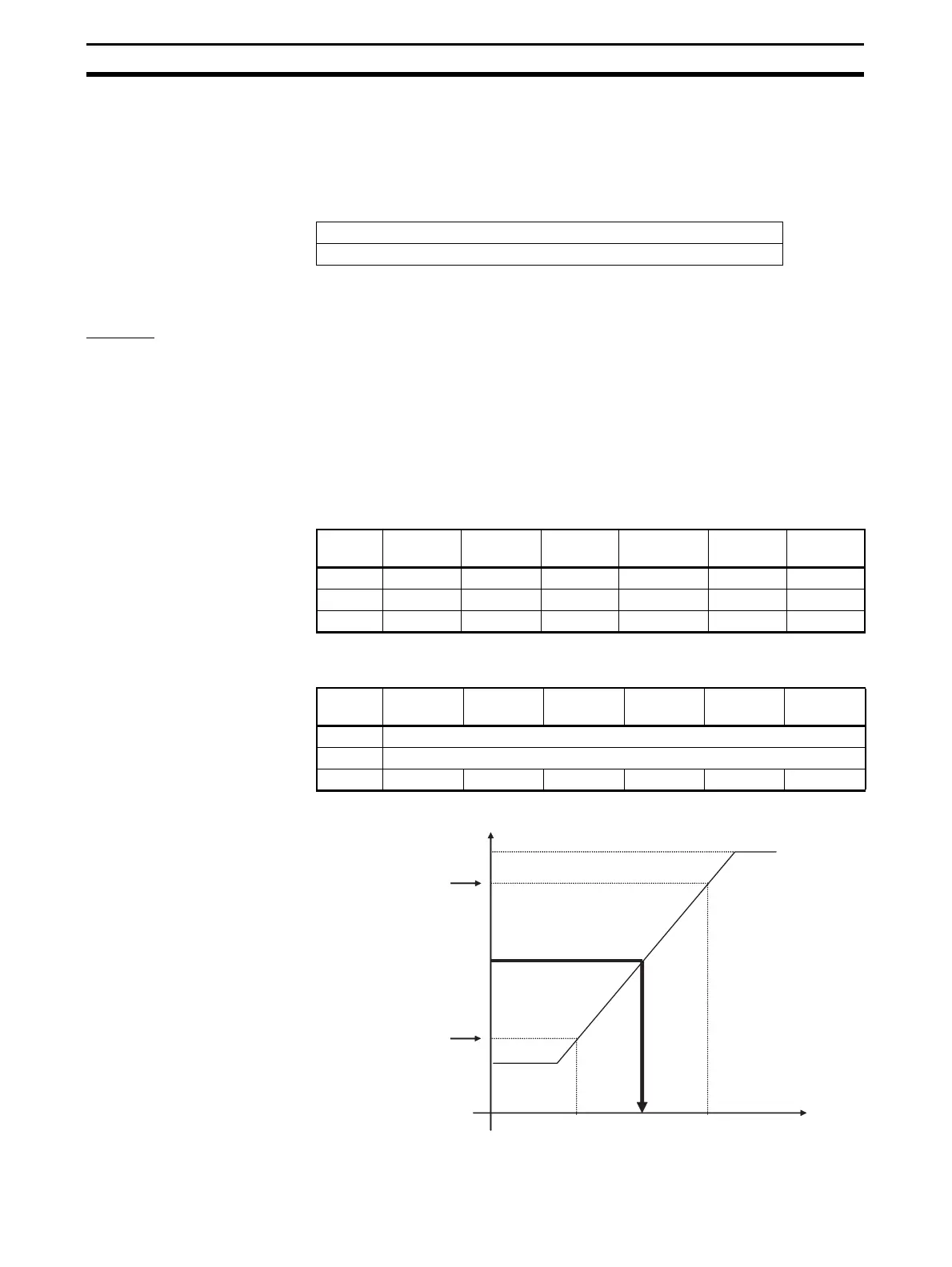
User Scaling User scaling allows analog output values to be scaled to user-defined values.
The conversion values for 100% and 0% are set using the Setting Tool.
15 8 7 0
Analog output value for Output 0
Analog output value for Output 1
Output
range
0 to 5 V 0 to 10 V 1 to 5 V –10 to 10 V 0 to
20 mA
4 to
20 mA
100% 5,000 mV 10,000 mV 5,000 mV 10,000 mV 20,000 μA 20,000 μA
0% 0000 mV 0000 mV 1,000 mV –10,000 mV 0000 μA 4,000 μA
Off-wire --- --- 7FFF hex --- --- 7FFF hex
Input
range
0 to 5 V 0 to 10 V 1 to 5 V –10 to
10 V
0 to
20 mA
4 to
20 mA
100% Set using Setting Tool (–28,000 to 28,000)
0% Set using Setting Tool (–28,000 to 28,000)
Off-wire --- --- 7FFF hex --- --- 7FFF hex
Scaling value
100% value set by
user (scaling point 2)
Output conversion
0% value set by user
(scaling point 1)
Output signal range
0%
100%

 Loading...


