Regular Payload Series-Hardware Installation Manual TM5 Series 32
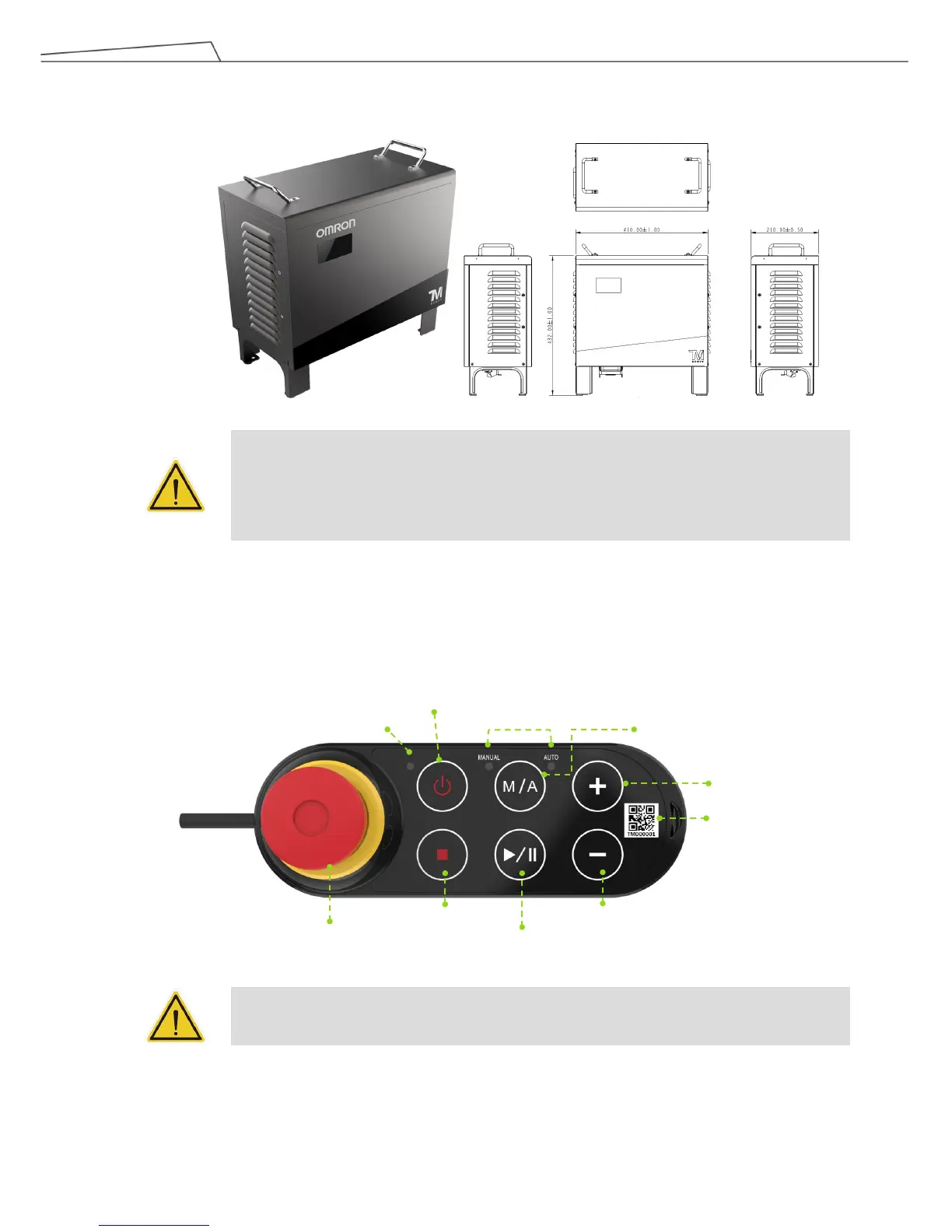
4.2.3 Control Box
CAUTION:
The control box can be placed on the floor or in your working cell. Note that 5 cm clearance
should be left at both sides for air flow.
4.2.3.1 Robot Stick
The Robot Stick has 6 function buttons, 3 indicator lights, 1 Emergency Switch, and 1 QR-code. Their
functions are as follow: