Regular Payload Series-Hardware Installation Manual TM5 Series 66
7. Maintenance and Repair
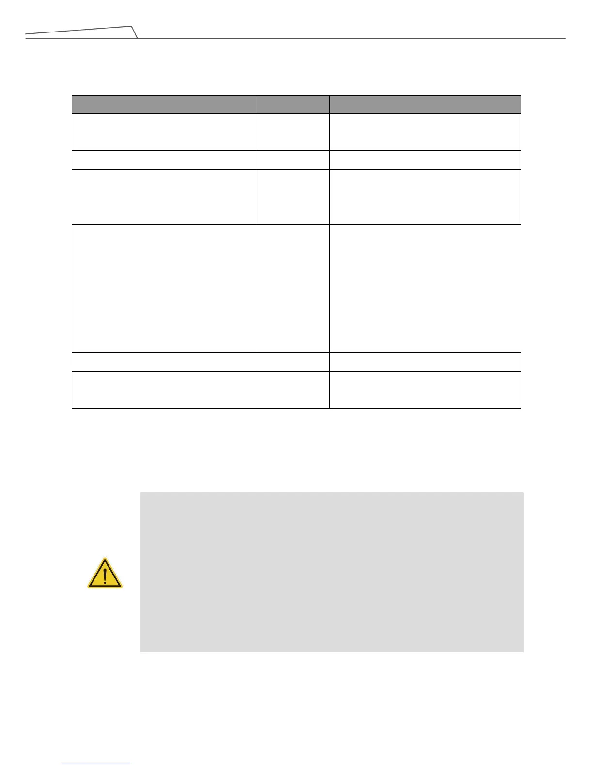
The following table gives a summary of the preventive maintenance procedures and guidelines:
Items Period Remark
Warning, Safety labels 1 week
Ensure labels are present and legible.
Replace them if necessary.
Check Filter 1 month Replace filter every 3 months.
Check Emergency Switch 1 month
Press the Emergency Switch and the IO
E-Stop in open-loop status. Verify that each
shuts off power.
Check Safeguard Ports (A, B) 1 month
When the Safeguard A Port is in the
open-loop state, the indication light of current
mode will be constantly flashing.
When the Safeguard B Port is in the
open-loop state, the purple light will be
alternating between the indication light of the
current mode.
Check Robot Mounting Screws 3 months Follow ”4.2.1.6 Robot Arm Installation”
EMO button (SEMI version only) 6 months
Press the EMO button. Verify that power
shuts off.
Only the legal distributor or authorized service center should repair the TM Robot. The user should not repair it by
himself or herself.
DANGER:
Before performing maintenance or service record the details of each setting for the robot for
normal operation. Make
normal operation, including but not limited to:
- Safety Software Settings
- Safety I/O
- Preset operation project
- TCP Settings
- I/O Settings
- I/O Wiring