Regular Payload Series-Hardware Installation Manual TM5 Series 48
5.4 Tool End I/O Interface
There are two small connectors on the tool end of the robot: The 8-pin connector is for digital I/O The 5-pin
connector is for analog I/O..
5.4.1 I/O Terminals
The tool end 24V has a maximum output current of 1.5A. If overloaded, overload protection is activated
and the robot will turn off the 24V output power.
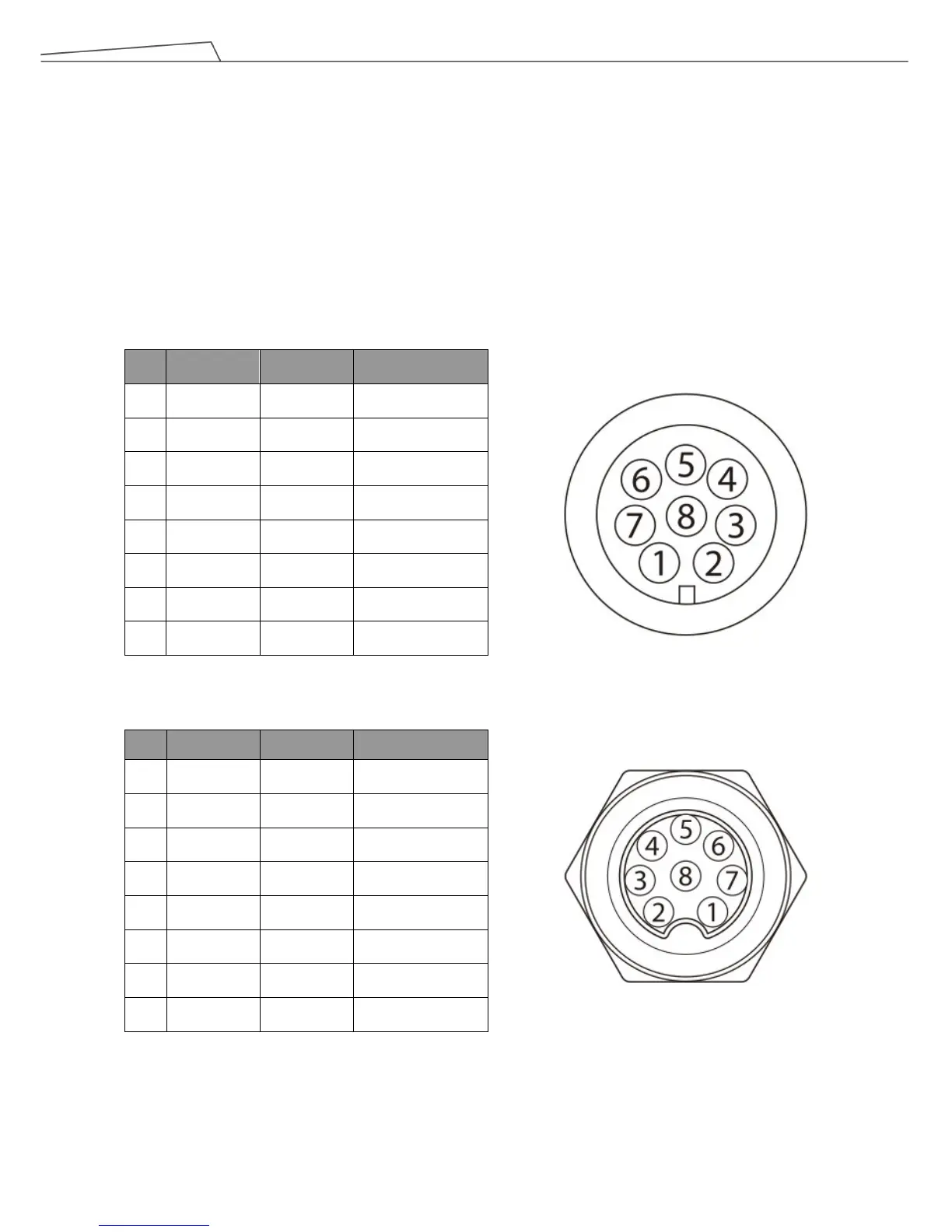
8-pin digital I/O connectors of Cable
8-pin digital I/O connector of Robot
Pin Wire color Pin define
1 Brown +24v 24V output
2 Red DI_0 Digital Input0
3 Orange DI_1 Digital Input1
4 Yellow DI_2 Digital Input2
5 Green DO_0 Digital Output0
6 Blue DO_1 Digital Output1
7 Purple DO_2 Digital Output2
8 Black +0V +0v
Pin Wire Color Pin Define
1 Brown +24v 24V output
2 Red DI_0 Digital intput0
3 Orange DI_1 Digital intput1
4 Yellow DI_2 Digital intput2
5 Green DO_0 Digital outtput0
6 Blue DO_1 Digital outtput1
7 Purple DO_2 Digital outtput2
8 Black +0V +0V