Regular Payload Series-Hardware Installation Manual TM5 Series 60
(1 cable)
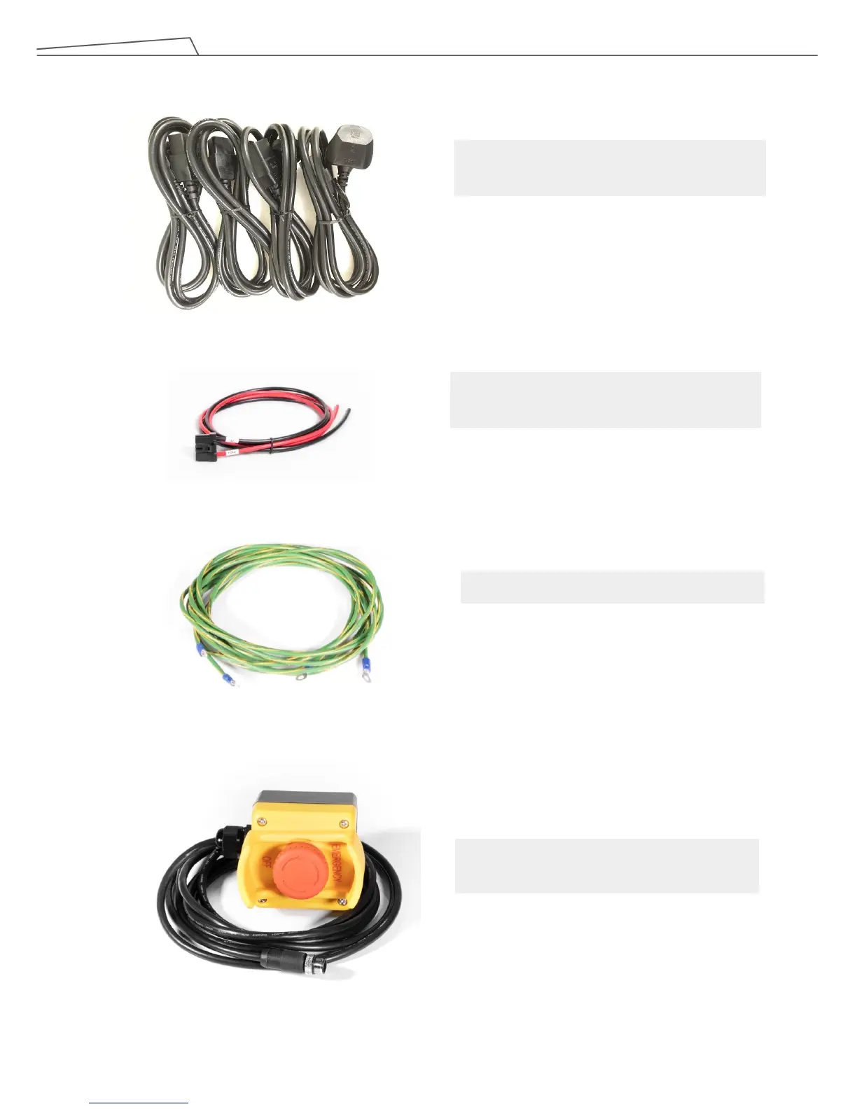
Power cable of the control box
(TM5M-700 / TM5M-900)
(4 cables, Type B, I, G, F)
Power cable of the control box
(TM5-700 / TM5-900)
Ground Wire
(1 pack)
SEMI Emergency OFF Switch
(SEMI Series only)
(1 pack)