1500 North Belcher Road, Clearwater, FL 33765 • Tel (727) 447-6140 • Fax (727) 442-5699 • sales@onicon.com
D-100 Display Module BACnet Installation and Operation Guide 04/12 - 0635-2 Page 9
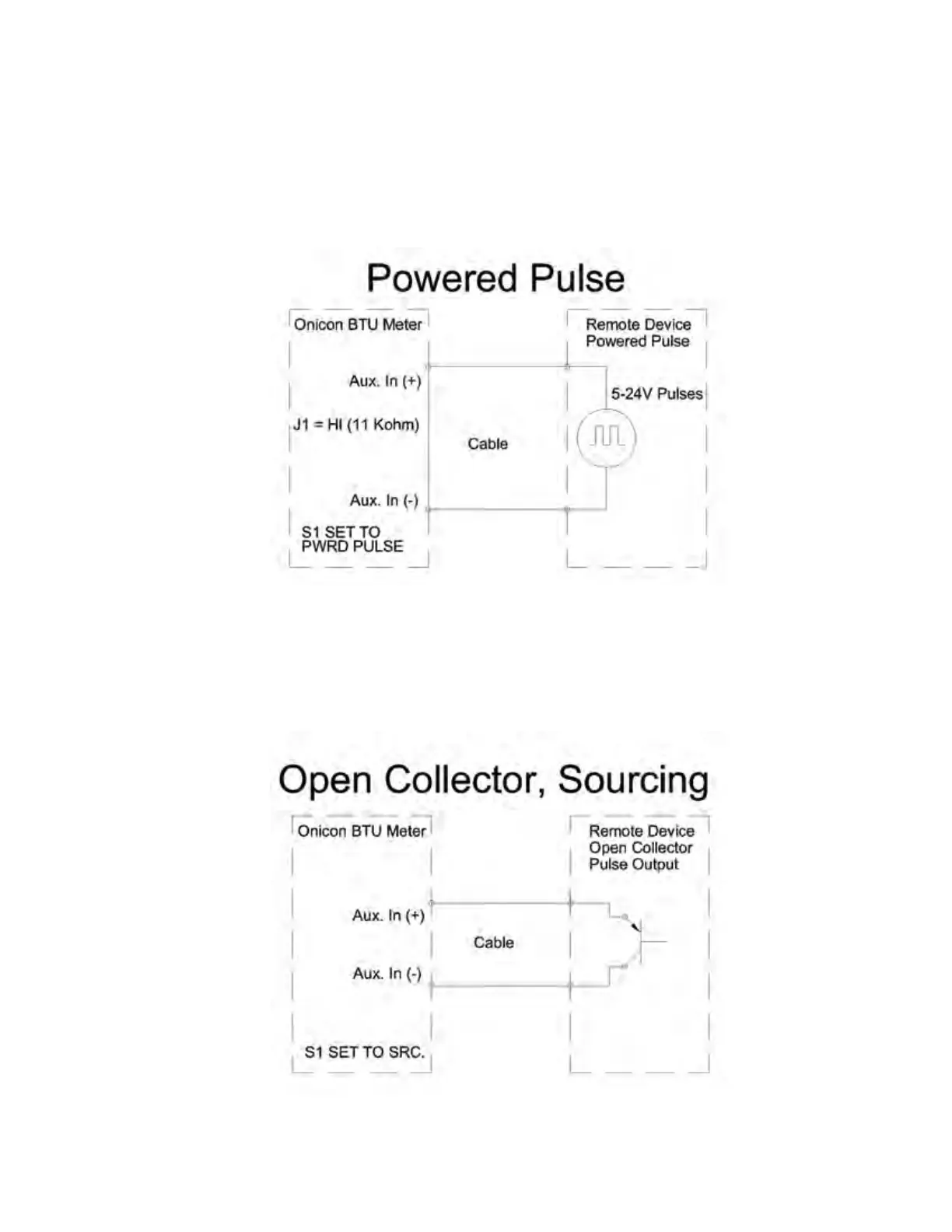
Powered Pulse:
This type of output refers to a pulse which has an associated voltage with it (see Fig. 2).
Set the selector switch, S1 to Pwrd Pulse. The allowable voltage range is 5-24 VDC. The
input impedance is set at the factory to be 11 KOHM via the impedance selector jumper
(J1, see Fig. 1). A lower impedance, 3 KOHM can be selected if required by the instrument
providing the pulse output. Consult the instrument manufacturer or ONICON if you are
uncertain as to the proper jumper selection.
Fig. 2
Open Collector (Sourcing):
This type of output refers to an open Collector Switch congured for a sourcing function
(see Fig. 3). Set the selector switch, S1 to SRC. The switch must be rated for at least 20mA
at 20VDC.
Fig. 3

 Loading...


