U
U
s
s
e
e
r
r
m
m
a
a
n
n
u
u
a
a
l
l
9
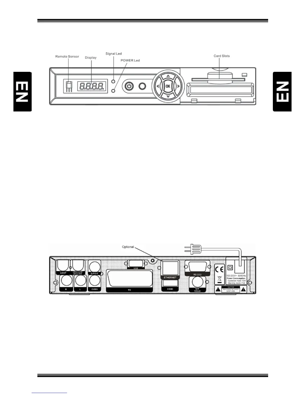
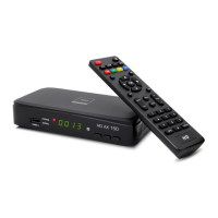
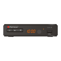
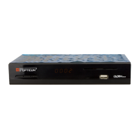
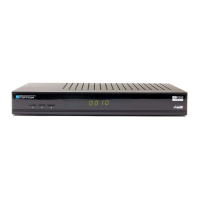
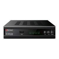
6. Front panel
POWER: To switch the receiver power on/stand by
MENU KEY: To enter into the main menu.
←,→: To adjust volume level, or to move cursor left or right in the menu
↑, ↓: To change channels, or to move cursor up or down in the menu
OK KEY: To see TV/Radio channel list, or to confirm in the menu.
Remote Sensor: Detects infrared signal from remote control unit
Power Led: Lights up while the receiver is power on
Signal Led: When receiving signal is strong, the signal led is lighted.
Display(4-Digit/7-Segment): Indicates operating status of receiver
Card Slot: Smart Card Interface for CONAX cards.
Insert the smart card chip side up!
Common Interface: Socket for Conditional Access Modules CAM (optional)
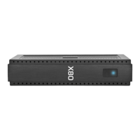
7. Rear panel
Please refer to the diagram above for all possible connections of your receiver
Do not connect the unit to the mains socket until all other connections have been made and checked.
Your configuration can vary depending on model.
LNB IN 13/18V: This port is to connect the coaxial cable from LNB/Dish. Max. 500mA
LOOP: This enables the connection of another receiver. (Optional)
R, L (AUDIO OUT): These RCA connectors are used to connect any external audio amp or system.
CVBS: This RCA connector is used to connect any external video.
S/PDIF: This RCA connector is used to connect external digital audio system.