If the Mode is set to Broadcast, messages in the Message Buffer will be output
immediately. If another event is captured while a message is being sent, it will be
queued in the buffer until the first message completes, then the next message will
be sent.
If the Mode is set to Request, messages in the Message Buffer are only sent when
the Request Character is received.
The output format used is selected among a small group of formats with the capability to
output data at 5ns resolution. Event Broadcast Output formats are detailed in "Event
Broadcast Time Code Formats" on page327.
To configure the Event Broadcast functionality:
1.
Configure the multi-I/O connector pinout to create the Event Input and Event
Broadcast ports:
Enable the Event Broadcast output. Navigte to MANAGEMENT >
NETWORK > Pin Layout. Click on the plus sign on the layout screen and
scroll down the Signal Type until you select ATC_OUT | RS232_EVENT.
This option must be configured on the 9 & 10 pins. Click submit.
Enable the Event Input. Click on the plus sign again, scroll down the Signal
Type and select GPIO_IN | DCLS_TTL. This option must be configured on
the 11 & 12 pins. Click submit.
2.
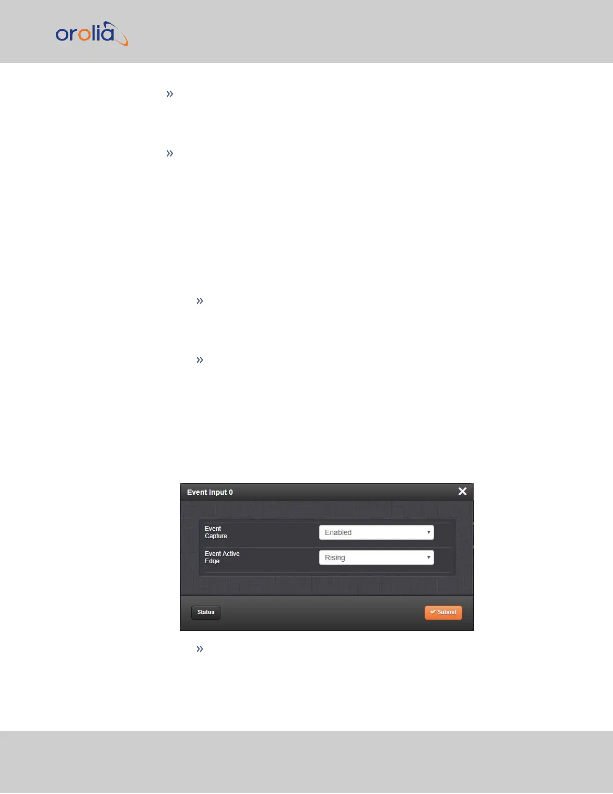
Configure the input settings. Navigate to INTERFACES > REFERENCES >
EVENTINPUT 0, or to INTERFACES > OPTION CARDS: Event Input 0. The
status window will display, providing information on the current settings: the Event
Capture and Event Active Edge settings, as well as the Last Event Message.
3.
Click the Edit button to open the configuration window:
Event Capture: Enables the processing of events on the Event Input (pins 11
& 12). When set to “Disabled”, no event messages will be queued. When set
2.7 Configuring Inputs/Outputs
CHAPTER 2 • VersaSync User Manual Rev. 7.0
55