Appendix
FPΣ User's Manual
296
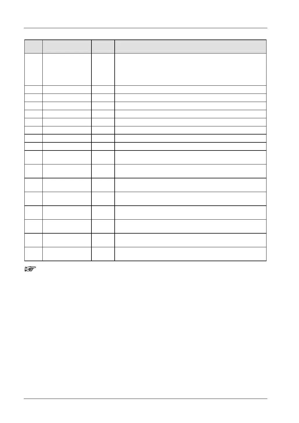
No.
Name Default Values
401
High-speed counter:
Channel 3
Unused
• Incremental input (X4)
• Incremental input (X4), Reset input (X5)
• Decremental input (X4)
• Decremental input (X4), Reset input (X5)
402
Pulse catch input: X0 Disable Disable/Enable
402
Pulse catch input: X1 Disable Disable/Enable
402
Pulse catch input: X2 Disable Disable/Enable
402
Pulse catch input: X3 Disable Disable/Enable
402
Pulse catch input: X4 Disable Disable/Enable
402
Pulse catch input: X5 Disable Disable/Enable
402
Pulse catch input: X6 Disable Disable/Enable
402
Pulse catch input: X7 Disable Disable/Enable
403
Interrupt input:
X0→Interrupt 0
Unused Rising edge/Falling edge
403
Interrupt input:
X1→Interrupt 1
Unused Rising edge/Falling edge
403
Interrupt input:
X2→Interrupt 2
Unused Rising edge/Falling edge
403
Interrupt input:
X3→Interrupt 3
Unused Rising edge/Falling edge
403
Interrupt input:
X4→Interrupt 4
Unused Rising edge/Falling edge
403
Interrupt input:
X5→Interrupt 5
Unused Rising edge/Falling edge
403
Interrupt input:
X6→Interrupt 6
Unused Rising edge/Falling edge
403
Interrupt input:
X7→Interrupt 7
Unused Rising edge/Falling edge
• If the same input has been set as high-speed counter input,
pulse catch input or interrupt input, the following order of
precedence is effective: High-speed counter → Pulse catch →
Interrupt.
• If reset input settings overlap for channel 0 and channel 1, the
channel 1 setting takes precedence. If reset input settings
overlap for channel 2 and channel 3, the channel 3 setting takes
precedence.
• The input modes two-phase, incremental/decremental, or
incremental/decremental control require a second channel. If
channel 0 or channel 2 have been set to one of these modes, the
settings for channel 1 and channel 3, respectively, will be
invalid.
• The settings for pulse catch inputs and interrupt inputs can only
be specified in the system registers.