Home
Panasonic
Stereo System
SC-HC40PC
Panasonic SC-HC40PC User Manual
5
of 1
of 1 rating
135 pages
Give review
Manual
Specs
To Next Page
To Next Page
To Previous Page
To Previous Page
Loading...
19
6
O
pe
rat
ing In
str
uc
tions
6.1.
CD Door
A
ssembly
Jam
6.1.1.
Removing the Disc
Step 1 :
Insert a flat
head screwdriver int
o the hole behi
nd the
CD Door Assem
bly and pus
h the Cam Gea
r from poin
t A to B.
Step 2 :
Gently p
ush the
CD Door Ass
embly as
arrow shown
until th
e Disc is
fully in
sight.
Ste
p
3 :
Remove the Disc
.
18
20
Table of Contents
Default Chapter
1
Table of Contents
1
1 Safety Precautions
4
General Guidelines
4
Before Repair and Adjustment
5
Caution for Fuse Replacement
5
Protection Circuitry
5
Safety Part Information
5
2 Warning
6
Prevention of Electro Static Discharge (ESD) to Electrostatically Sensitive (ES) Devices
6
Precaution of Laser Diode
7
Service Caution Based on Legal Restrictions
8
Handling Precaution for Traverse Unit
9
3 Service Navigation
10
Service Information
10
4 Specifications
11
5 Location of Controls and Components
12
Main Unit & Remote Control Key Button Operations
12
FM/AM Connections
13
Disc Operations
14
Ipod/Iphone Operations
16
Bluetooth Operation
17
USB Operation
18
6 Operating Instructions
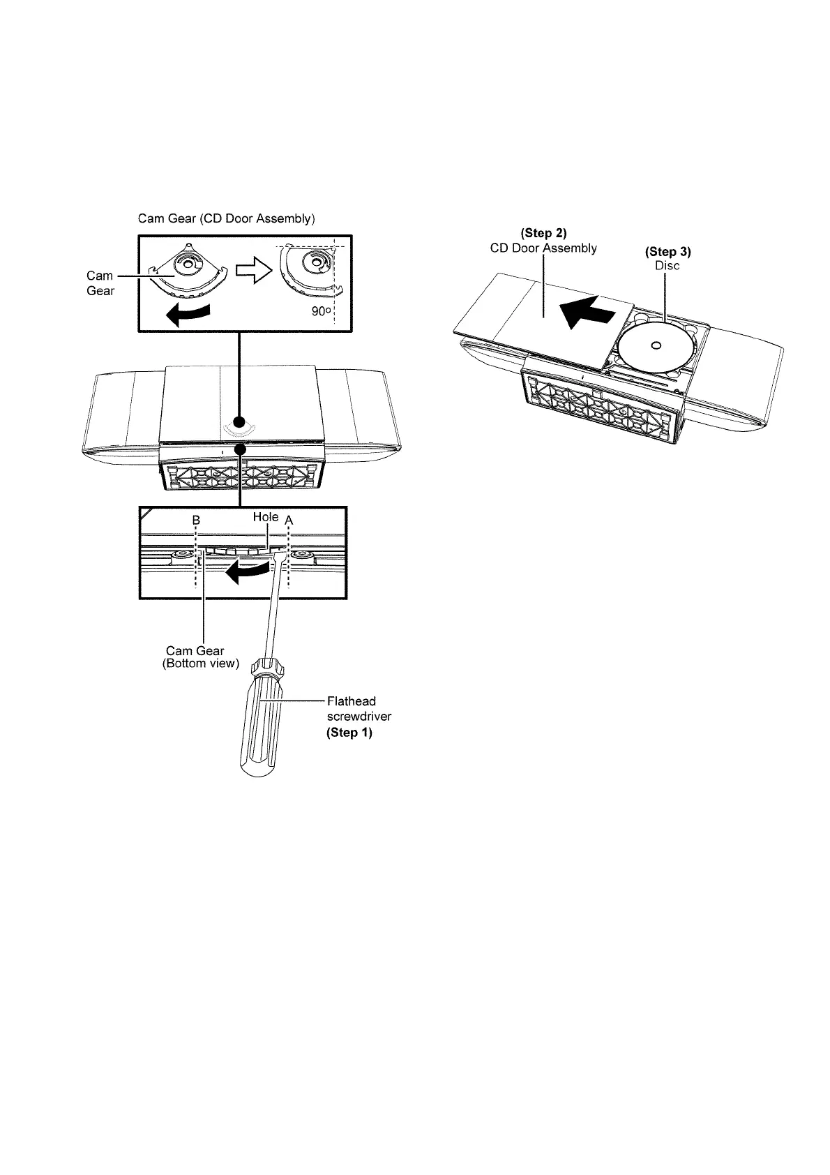
19
CD Door Assembly Jam
19
7 Self Diagnostic and Doctor Mode Setting
21
Self Diagnostic Mode
21
Self Diagnostic Error Code
22
Doctor Mode
23
Sales Demonstration Lock Function Mode
26
8 Service Fixture & Tools
27
9 Disassembly and Assembly Instructions
28
Disassembly Flow Chart
29
Types of Screws
30
Main Parts Location Diagram
30
Disassembly of Stand Unit
31
Replacement of CD Door Assembly
31
Disassembly of Net Frame Assembly
33
Disassembly of Front Panel Block
35
Disassembly of Top Ornament Unit
36
Disassembly of Button P.C.B
37
Disassembly of Passive Radiator (SP5)
37
Disassembly of Passive Radiator (SP6)
38
Disassembly of Front Speaker (SP1)
38
Disassembly of Front Speaker (SP2)
40
Disassembly of Passive Radiator (SP3)
42
Disassembly of Passive Radiator (SP4)
42
Disassembly of Traverse Unit
43
Disassembly of Traverse Cover & Traverse Assembly
43
Disassembly of CD Servo P.C.B
44
Disassembly of USB P.C.B
45
Disassembly of USB Lid
46
Disassembly of Headphone/Aux P.C.B
47
Disassembly of PCB Block
48
Disassembly of SMPS P.C.B
50
Replacement of Switching Regulator IC (IC5701)
52
Replacement of Voltage Regulator IC (IC2910)
53
Replacement of Diode (D5802)
55
Disassembly of Horizontal Main P.C.B. and Vertical Main P.C.B
56
Replacement of Power Amplifier IC (IC1)
56
Disassembly of Bluetooth P.C.B
58
Disassembly of Tuner P.C.B
58
Disassembly of Fan Unit
59
Disassembly of Panel P.C.B
60
Disassembly of IR P.C.B. and Ipod/Iphone Switch P.C.B
61
Disassembly of Motor P.C.B., Door Switch P.C.B. and Interlock Switch P.C.B
62
Disassembly of Motor Assembly
65
Disassembly of Ipod/Iphone P.C.B
66
10 Service Position
70
Checking & Repairing of Panel P.C.B
70
Checking & Repairing of CD Servo P.C.B
70
Checking & Repairing of SMPS P.C.B
71
Checking & Repairing of Horizontal Main P.C.B
73
Checking & Repairing of Vertical Main P.C.B. (Side A)
74
Checking & Repairing of Vertical Main P.C.B. (Side B)
76
Checking & Repairing of USB P.C.B
77
11 Voltage Measurement & Waveform Chart
79
CD Servo P.C.b
79
Vertical Main P.C.b. (1/3)
80
Vertical Main P.C.b. (2/3)
81
Vertical Main P.C.b. (3/3)
82
Horizontal Main P.C.b
82
Panel P.C.b
83
Button P.C.b
83
Tuner P.C.b
83
Ir P.C.b
83
Smps P.C.b
84
Usb P.C.b
84
Waveform Chart
85
12 Illustration of IC's, Transistors and Diodes
86
13 Overall Simplified Block
87
14 Block Diagram
89
Servo/System Control(1/2) Block Diagram
89
Servo/System Control(2/2) Block Diagram
90
IC Terminal Chart (Servo/System Control)
91
Bluetooth Block Diagram
92
Audio Block Diagram
93
Power Supply(1/2) Block Diagram
94
Power Supply(2/2) Block Diagram
95
15 Wiring Connection Diagram
96
16 Schematic Diagram Notes
97
17 Schematic Diagram
99
CD Servo Circuit
99
Vertical Main Circuit (1/4)
100
Vertical Main Circuit (2/4)
101
Vertical Main Circuit (3/4)
102
Vertical Main Circuit (4/4)
103
Horizontal Main Circuit
104
Panel & Button Circuit
105
Tuner, Headphone/Aux, Ir & Motor Circuit
106
Ipod/Iphone, Ipod/Iphone SWITCH, DOOR SWITCH & INTERLOCK SWITCH CIRCUIT
107
Smps Circuit
108
Usb Circuit
109
18 Printed Circuit Board
110
CD Servo P.C.b
110
Vertical Main P.C.b
111
Horizontal Main P.C.b
112
Panel, Button, Headphone/Aux & Motor P.C.b
113
TUNER, IR, Ipod/Iphone & Ipod/Iphone SWITCH P.C.B
114
Door Switch, Interlock Switch & Smps P.C.b
115
Usb P.C.b
116
19 Terminal Function of IC's
117
Ic801 (Rfkwmhc40Eg) Micro Processor IC
117
Ic7001 (Mn6627954Ama) IC Servo Processor
118
IC7002 (BA5948FPE2) IC 4CH Drive
119
20 Exploded View and Replacement Parts List
121
Exploded View and Mechanical Replacement Parts List
121
Electrical Replacement Parts List
127
5
Based on 1 rating
Ask a question
Give review
Questions and Answers:
Need help?
Do you have a question about the Panasonic SC-HC40PC and is the answer not in the manual?
Ask a question
Panasonic SC-HC40PC Specifications
General
Brand
Panasonic
Model
SC-HC40PC
Category
Stereo System
Language
English
Related product manuals
Panasonic SC-HC40
32 pages
Panasonic SC-HC400
20 pages
Panasonic SC-HC402
28 pages
Panasonic SC-HC40DB
24 pages
Panasonic SC-HC49
24 pages
Panasonic SC-HC4GK
132 pages
Panasonic SC-HC412
28 pages
Panasonic SC-HC410
28 pages
Panasonic SC-HC49DB
24 pages
Panasonic SC-HC05
10 pages
Panasonic SC-HC55
28 pages
Panasonic SC-HC58
32 pages