74
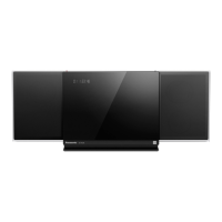
Step 18 : Connect 25P extension cable (RFKZHC30K1) from
CN7002 on the CD Servo P.C.B. to CN7002 on the Vertical
Main P.C.B..
Step 19 : Connect 11P cable at the connector (CN100) on the
Horizontal Main P.C.B..
Step 20 : Check and repair the Horizontal Main P.C.B. accord-
ing to the diagram shown.
10.5. Checking & Repairing of Verti-
cal Main P.C.B. (Side A)
Step 1 : Remove the Stand Unit.
Step 2 : Remove the CD Door Assembly.
Step 3 : Remove the Net Frame Assembly.
Step 4 : Remove the Front Panel Block.
Step 5 : Remove the Top Ornament.
Step 6 : Remove the Traverse Unit.
Step 7 : Remove the USB P.C.B..
Step 8 : Remove the Headphone/Aux P.C.B..
Step 9 : Remove the PCB Block.
Step 10 : Remove the Fan Unit.
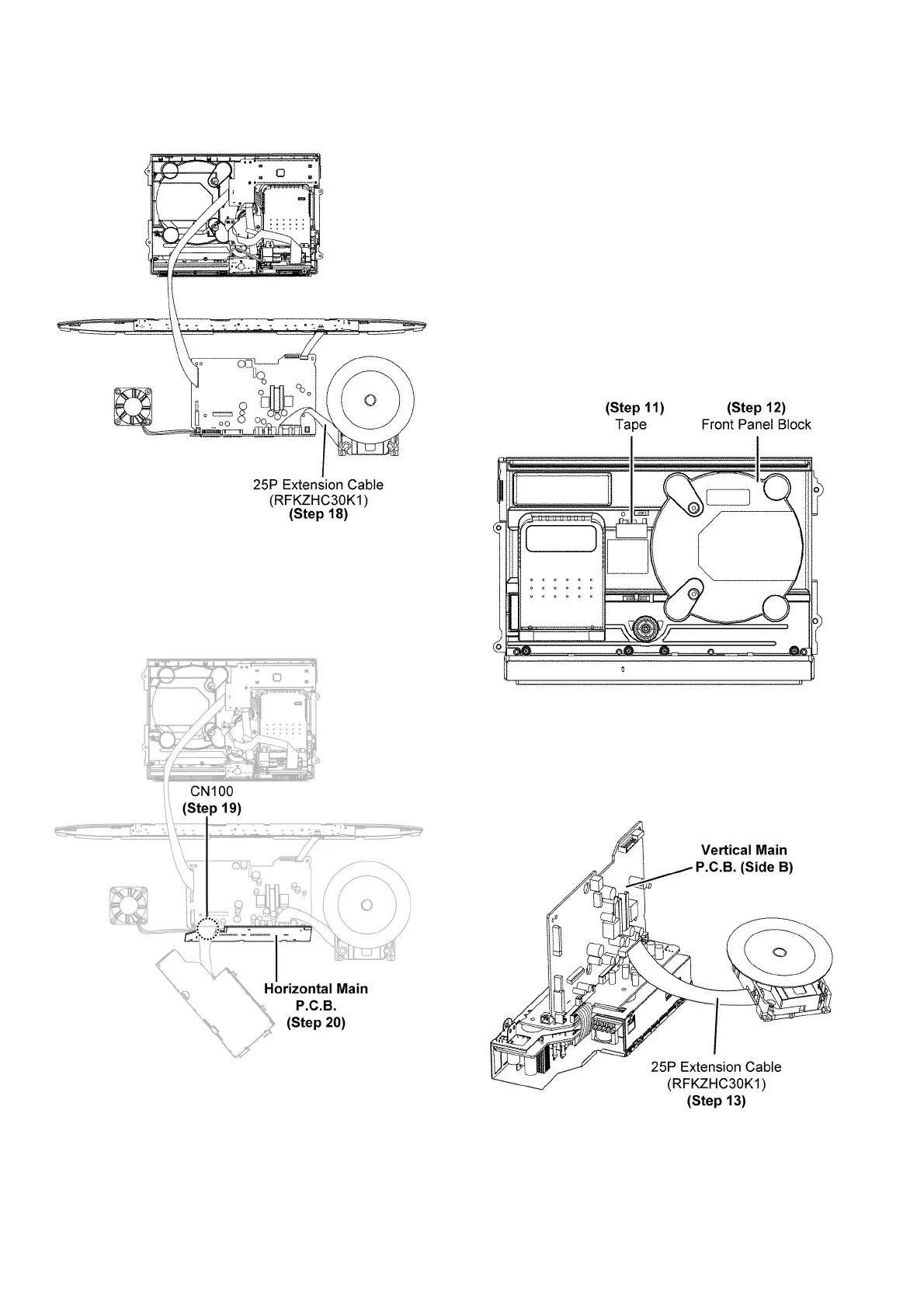
Step 11 : Use tape to keep the Switch depressed.
Step 12 : Flip over the Front Panel Block.
Step 13 : Connect 25P extension cable (RFKZHC30K1) from
CN7002 on the CD Servo P.C.B. to CN7002 on the Vertical
Main P.C.B..