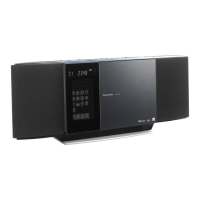
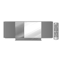
97
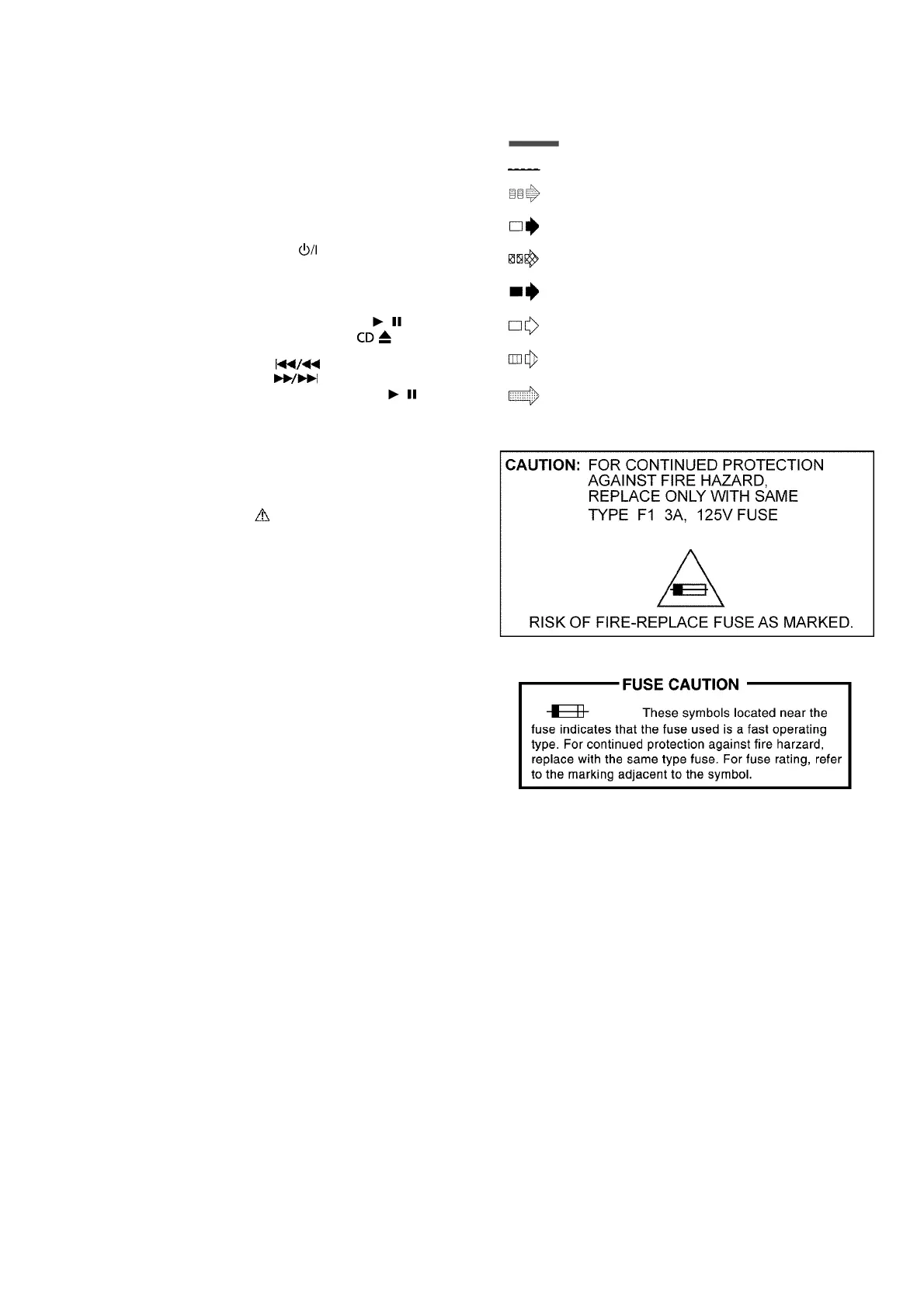
16 Schematic Diagram Notes
(All schematic diagrams may be modified at any time with
the development of new technology)
Notes:
• Important safety notice:
Components identified by mark have special characteris-
tics important for safety.
Furthermore, special parts which have purposes of fire-retar-
dant (resistors), high quality sound (capacitors), low-noise
(resistors), etc are used.
When replacing any of components, be sure to use only
manufacturer’s specified parts shown in the parts list.
• Resistor
Unit of resistance is OHM [Ω] (K=1,000, M=1,000,000).
• Capacitor
Unit of capacitance is μF, unless otherwise noted. F=Farads,
pF=pico-Farad.
• Coil
Unit of inductance is H, unless otherwise noted.
•
*
REF IS FOR INDICATION ONLY.
• Voltage and signal line
S641: LEFT switch.
S642: RIGHT switch.
S643: CENTER switch.
S644: INTERLOCK switch.
S645: iPod DOCK OPEN switch.
S901:
POWER switch ( ).
S902: iPod OPEN/CLOSE switch.
S903: USB PLAY/PAUSE switch.
S904: BLUETOOTH PLAY/PAUSE switch.
S905: FM/AM/AUX switch.
S906:
CD PLAY/PAUSE switch (CD / ).
S907:
CD OPEN/CLOSE switch ( ).
S908: STOP/PHONE OFF switch (I).
S911: REW switch ( ).
S912: FWD switch ( ).
S913:
iPod PLAY/PAUSE switch (iPod / ).
S914: VOL- switch.
S915: VOL+ switch.
S916: PHONE ON switch.
S7201: REST switch.
: +B Signal Line
: -B Signal Line
: CD Audio Input Signal Line
: AM/FM Signal Line
: Audio Output Signal Line
: AM Signal Line
: FM Signal Line
: iPod/iPhone/Aux/Mic Audio Input Signal
Line
: USB Signal Line