55
Chapter 2
Starting
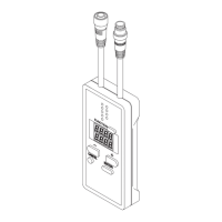
7. Setting of S-LINK V system side of SL-VGU1-C (CONFIG mode)
(1st controller)
(2nd controller)
(1st controller)
SL-VGU1-C
(2nd controller)
Setting of transmission mode
Setting of number of I/O control points
Setting of error 1
output operation
Setting of error 2
output operation
Setting of error 3
output operation
Setting of error 4
output operation
Setting of error 5
I/O setting 0
I/O setting 1
I/O setting 2
I/O setting 3
Output hold / clear
Buffer memory assignment
Setting of display to decimal /
hexadecimal number display
8. Wiring (CC-Link side)
Connect two SL-VGU1-Cs’ to the master.
Install the master unit next to the CPU unit.
Connect the terminal resistor to the master and the end SL-VGU1-C (station number ‘05’).
9. Wiring (S-LINK V system side)
Connect the S-LINK V I/O units to the corresponding SL-VGU1-C.
Setting of S-LINK V system side
1. Set the mode selection switch to CONFIG, and then turn on the power.
2. Various setting items will be displayed. Set these items considering the system conditions.
3. For a detailed description of setting, refer to page 47 ‘CONFIG Mode.’
Output hold
If the PLC CPU has a problem during operation, the output condition of the S-LINK V output unit can be held or
cleared. Set whether the output condition should be held or cleared.
Output of S-LINK V output unit
Output hold Holds the output condition.
Output clear Turns off the output.
Note: If an error (error 1 or 2) occurs on the S-LINK V system side, the output condition of the S-LINK V output unit will be held or cleared
depending on the set position of the output hold setting switch.

 Loading...


