73
Chapter 3
Functional Description
54321
ERR
G
D
0V
24V
0V
24V
FG
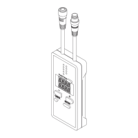
1. SELECT keys
block connector
2. Address display (Red)
7. Error indicator (Red)
6. Transmission
indicator (Green)
(Orange)
3. ENTER key
5. Mode selection switch
8. S-LINK V terminal
block connector
9. DeviceNet indicators
(Green, Red)
11. DeviceNet transmission
speed setting switches
10. DeviceNet address
setting switches
No. Designation Description
1
Hexadecimal indicator
(Orange)
●It indicates the display mode of the address display.
• Lights up: Hexadecimal display mode
• Turns off: Decimal display mode
2 Address display (Red)
●The display contents differ in 'RUN mode,' 'CHECK mode' and 'CONFIG mode.'
The mode can be changed with the mode selection switch.
<RUN mode>
• LEDs light up in each transmission mode (3 types), and trace out a rectangle in the clockwise direction.
• When an error occurs, the type of error is shown.
Note: When the cause of the error is removed, the error display can be erased by pressing ENTER key
and SELECT keys (2 types) simultaneously.
<CHECK mode>
• At rst, the recognized connected node number is displayed. Subsequently, the addresses are displayed
at every press of SELECT keys.
Connected node No.: I/O unit node No. is displayed in decimal / hexadecimal.
Address: I/O unit addresses are displayed successively in decimal / hexadecimal.
Note: In case of hexadecimal display, the hexadecimal indicator lights up.
• When an error occurs, the node number having the error and the error addresses are displayed succes-
sively.
<CONFIG mode>
• Each setting is displayed successively. The settings can be changed by using SELECT key.
• The display contents differ when power is switched on and when a change is made from RUN mode.

 Loading...

